Stereoscopic image display apparatus

a technology of stereoscopic image and display apparatus, which is applied in the direction of optics, instruments, optical elements, etc., can solve the problems of instantaneous generation and annihilation, no proposal for improving the viewing zone angle of the lens array, and the difficulty of performing such an operation, so as to reduce the amount of crosstalk and stray light

Inactive Publication Date: 2006-11-16
KK TOSHIBA
View PDF7 Cites 23 Cited by
  • Summary
  • Abstract
  • Description
  • Claims
  • Application Information

AI Technical Summary

Benefits of technology

[0018] The present invention has been made in view of the above circumstances, and an object thereof is to provide a stereoscopic image display apparatus where a crosstalk amount and stray light are reduced even if a viewing zone angle is wide or large.

Problems solved by technology

Since the curved face of the lens strongly affect image quality, when the lenticular lens sheet is used as the beam controlling element, it is difficult to perform such an operation, namely, instantaneous generation and annihilation, as compared with use of the slit member as the beam controlling element.
In JP-A-P2004-258631, however, there is no proposal about improvement of a viewing zone angle in the lens array.
Therefore, an aberration becomes large and crosstalk increases, which results in degradation of image quality.
In the first method, since the difference between recess and projection of a lens is small, it is easy to produce the lens, but even if the lens is formed in an elliptical shape in order to reduce aberration, reduction is not achieved so much, because the difference is small.
However, there is such a problem that even if a radius of curvature is reduced in order to shorten a focal length of a lens extremely, converging can not be achieved due to a small difference in refractive index.
As one of the problems regarding production of a biconvex lens, there is necessity of positioning both convex lenses to each other and keeping a gap between the convex lenses constant.
As a further problem, when a lens array is used as the beam controlling element for the stereoscopic image display apparatus, not only converging of light rays in a direction of an optical axis of a lens when the lens is viewed from its front face but also converging of light rays at a position deviated from an optical axis of the lens when the lens is viewed at a viewing zone angle θ must be taken into consideration.
Since the above event injures or deteriorates a three-dimensional image display performance, any countermeasure must be taken.
As another problem, it is necessity of causing a center of a viewing zone to a central viewer in the stereoscopic image display apparatus.
Unless the optical axes coincide with each other, there occurs such a problem that stray light increases.

Method used


Image

  • Stereoscopic image display apparatus
  • Stereoscopic image display apparatus
  • Stereoscopic image display apparatus

Examples


first embodiment

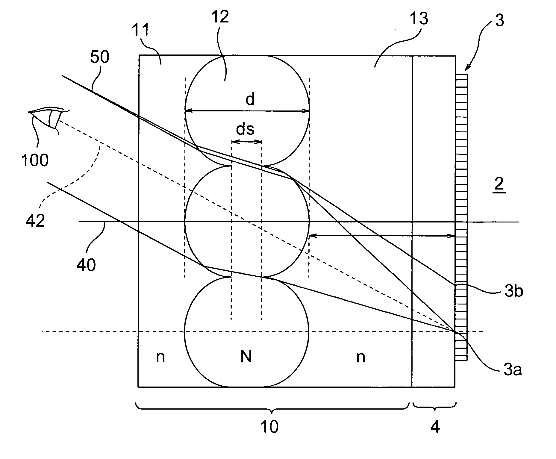
[0090] A stereoscopic image display apparatus according to a first embodiment of the present invention will be explained with reference to FIG. 1 to FIG. 12. FIG. 1 is a horizontal sectional view of a stereoscopic image display apparatus according to the embodiment.

[0091] A stereoscopic image display apparatus according to the embodiment is provided with a flat display device (also, called “a two-dimensional display device) 2 and a beam controlling element 10. The flat display device 2 is a liquid crystal display device, for example, and it is provided with a display portion 3 for displaying image information which has a plurality of pixels arranged in a matrix manner, and a protection substrate 4 for protecting the display portion 3 which is composed of a transparent member, for example, a glass.

[0092] The beam controlling element 10 is disposed on a front face of the flat display device 2 (on a side of a viewer 100) and is provided with a lens array 11, a lens array 12, and a le...

second embodiment

[0117] Next, a stereoscopic image display apparatus according to a second embodiment of the invention will be explained with reference to FIGS. 14 to 23. FIG. 14 is a horizontal sectional view of a stereoscopic image display apparatus according to the embodiment.

[0118] A stereoscopic image display apparatus according to the embodiment is provided with a flat display device (also, called “a two-dimensional display device) 2 and an beam controlling element or a beam controlling element 10. The flat display device 2 is a liquid crystal display device, for example, and it is provided with a display portion 3 for displaying image information which has a plurality of pixels arranged in a matrix manner, and a protection substrate 4 for protecting the display portion 3 which is composed of a transparent member, for example, a glass.

[0119] The beam controlling element 10 is provided on a front face of the flat display device 2, and it is provided with lens arrays 15, 16, a transparent subs...


PUM

PropertyMeasurementUnit
refractive indexaaaaaaaaaa

Abstract

It is possible to reduce a crosstalk amount and stray light even if a viewing zone angle is wide or large. A stereoscopic image display apparatus includes: a flat display device and a beam controlling element provided on a front face of the flat display device. The beam controlling element includes: a first lens array having a plurality of lenses, a second lens array having a plurality of lenses, and a third lens array provided between the first lens array and the second lens array and having a plurality of lenses. The third lens array is configured such that each lens thereof on the first lens array side coincides with a corresponding lens thereof on the second lens array, and refractive indexes of the first and the second lens arrays are approximately the same, and a refractive index of the third lens array is different from the refractive indexes of the first and the second lens arrays.

Description

CROSS-REFERENCE TO RELATED APPLICATION [0001] This application is based upon and claims the benefit of priority from prior Japanese Patent Application No. 2005-95607 filed on Mar. 29, 2005 in Japan, the entire contents of which are incorporated herein by reference.BACKGROUND OF THE INVENTION [0002] 1. Field of the Invention [0003] The present invention relates to a stereoscopic image display apparatus. [0004] 2. Related Art [0005] A method which record a stereoscopic image utilizing any means and reproduces the stereoscopic image, called an integral photography system for displaying many parallax images (hereinafter, called “IP systems”) or a beam reproducing system has been known. It is assumed that a viewer observes or views an object or a point. When an angle of the object positioned at a close distance defined by his / her left and right eyes is represented as α and an angle of the object positioned at a far distance defined by his / her left and right eyes is represented as β, α an...

Claims


Application Information

Patent Timeline
Patent Type & Authority Applications(United States)
IPC IPC(8): G02F1/1335G02B30/27
CPCG02F1/133526G02B27/2214G02B30/27
Inventor TAKAGI, AYAKOTAIRA, KAZUKIHASEGAWA, REIKIZU, YUKOHIRAYAMA, YUZOFUKUSHIMA, RIEKOSAISHU, TATSUOKOBAYASHI, HITOSHI
Owner KK TOSHIBA
Why Eureka
Try Eureka