Multi-channel optical coupler

An optical coupler and coupling module technology, applied in the field of optical communication

Pending Publication Date: 2021-01-01
이네오스엘엘씨
View PDF5 Cites 0 Cited by
  • Summary
  • Abstract
  • Description
  • Claims
  • Application Information

AI Technical Summary

Problems solved by technology

[0007] However, significant disadvantages or problems with such arrangements include additional size and cost due to the need for separate optical and electronic components for each fiber optic connection

Method used


Image

  • Multi-channel optical coupler
  • Multi-channel optical coupler
  • Multi-channel optical coupler

Examples


Embodiment Construction

[0048] As briefly mentioned above, the separation of each fiber in multi-fiber optical coupling has the advantage that crosstalk between channels on the respective fibers can be effectively reduced and / or minimized. However, as also mentioned above, there are significant disadvantages or problems with such arrangements, including the additional size and cost of the coupling member being duplicated for each fiber optic connection. Accordingly, there is a need for an improved multi-fiber optical coupler that is cost-effective as compared to per-fiber optical coupling arrangements while achieving crosstalk performance similar to such per-fiber optical coupling arrangements.

[0049] Crosstalk in fiber optic applications can be illustrated by an exemplary arrangement of four fibers F1-F4, each having four wavelengths λ1-λ4. In this arrangement, there are sixteen channels, namely (F1, λ1) to (F4, λ4). However, if each of F1-F4 uses a separate optical coupler, each channel (e.g., (...


PUM

PropertyMeasurementUnit
thicknessaaaaaaaaaa

Abstract

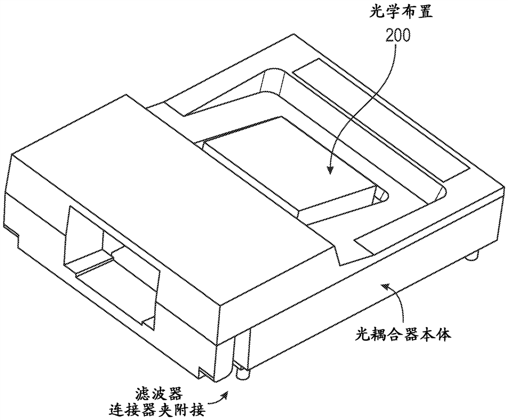
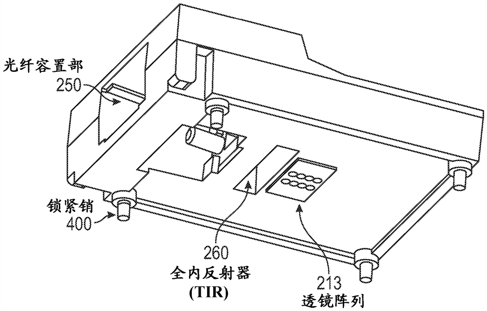
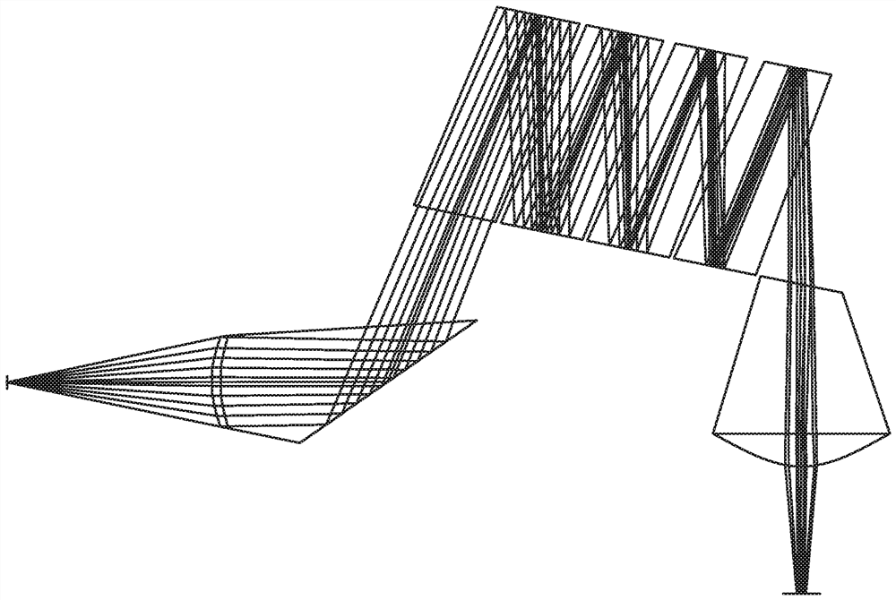
Exemplary multi-channel optical couplers include a molded coupling module comprising a first surface, a second surface, a lens array receptacle, and fiber receptacles for optical fibers; an optical arrangement comprising: a particular surface carrying a reflective coating, and a further surface carrying a plurality of optical filters, each configured to pass a single optical wavelength; a first lens array configured such that each lens is optically aligned with the plurality of optical filters via at least the reflective coating, and with a position, within a particular fiber receptacle, corresponding to the end of a particular optical fiber; a second lens array arranged with the second surface such that each lens is optically aligned with an optical filter. The optical block and lens arrays can be configured such that the optical coupler produces no more than -10 dB of crosstalk on any of the optical wavelengths passed by the optical filters.

Description

[0001] related application [0002] This application claims the benefit of priority to U.S. Provisional Patent Application No. 62 / 626,462, filed February 5, 2018, the entire disclosure of which is incorporated herein by reference for all purposes. technical field [0003] The present application relates generally to the field of optical communications, and more particularly to devices for coupling multiple optical channels (eg, wavelengths) onto two or more optical fibers. Background technique [0004] In wavelength division multiplexed optical communication systems, many different optical wavelength carriers provide independent communication channels in a single optical fiber. Future computing and communication systems place increasingly high demands on communication link bandwidth. Fiber optics are known to provide much higher bandwidth than conventional coaxial communications. Furthermore, the fiber bandwidth used by a single optical channel in a fiber waveguide is very...

Claims


Application Information

Patent Timeline
Patent Type & Authority Applications(China)
IPC IPC(8): G02B6/42G02B6/293
CPCG02B6/428G02B6/4214G02B6/4215G02B6/4249G02B6/4292G02B6/29367H04J14/0278
Inventor E·格兰S·弗吕格尔I·恩齐迪贝
Owner 이네오스엘엘씨
Why Eureka
Try Eureka