Differential transmission circuit, optical module and manufacturing method of differential transmission circuit

a technology of differential transmission circuit and manufacturing method, which is applied in the direction of waveguides, conductive pattern formation, instruments, etc., can solve the problems of increasing the crosstalk amount of the plurality of differential transmission lines included in the device, increasing the packaging density of wiring and components mounted on the printed circuit board, and reducing the width and area of the printed circuit board. , to achieve the effect of narrowing the region occupied, reducing the amount of crosstalk, and increasing the speed and packaging density

Active Publication Date: 2017-10-03
LUMENTUM JAPAN INC
View PDF18 Cites 0 Cited by
  • Summary
  • Abstract
  • Description
  • Claims
  • Application Information

AI Technical Summary

Benefits of technology

[0011]Further, in the printed circuit board illustrated in FIG. 2, arrangement and formation of the metal wiring 40 and the through via holes may be omitted, and the channel pitch Pa may be set narrower than 1.8 mm, to thereby reduce the region occupied by the receiver-side differential transmission line 2 and the transmitter-side differential transmission line 3. However, narrowing the channel pitch Pa causes a problem of increase in crosstalk between the differential transmission lines.
[0015]The present invention has been made in view of the above-mentioned circumstances, and it is an object of the present invention to provide a differential transmission circuit including a plurality of transmission lines, and an optical module capable of, in the optical module having a plurality of differential transmission lines arranged thereon, reducing the crosstalk amount between the differential transmission lines, narrowing the region occupied by the differential transmission line, and increasing the speed and packaging density.
[0029]According to one embodiment of the present invention, the differential transmission circuit including the plurality of transmission lines and the optical module are provided, which are capable of, in the optical module having the plurality of differential transmission lines arranged thereon, reducing the crosstalk amount between the differential transmission lines, narrowing the region occupied by the differential transmission line, and increasing the speed and packaging density.

Problems solved by technology

As the device is downsized, the crosstalk of the plurality of differential transmission lines included in the device becomes a more serious problem.
Further, as the optical module is downsized, the width and area of the printed circuit board are accordingly further reduced, which causes increase in packaging densities of wiring and components mounted on the printed circuit board.

Method used


Image

  • Differential transmission circuit, optical module and manufacturing method of differential transmission circuit
  • Differential transmission circuit, optical module and manufacturing method of differential transmission circuit
  • Differential transmission circuit, optical module and manufacturing method of differential transmission circuit

Examples


first embodiment

[0059]Referring to the accompanying drawings, a first embodiment of the present invention is described below. In the drawings, the same or similar components are denoted by the same reference symbols, and repetitive description thereof is omitted. Note, in this specification, a transmission circuit may include one or a plurality of transmission lines. Further, one transmission line may be a transmission line having one or more channels.

[0060]FIG. 4 is a schematic view of an optical module 1 (optical transmission device) according to this embodiment. As illustrated in FIG. 4, the optical module 1 according to this embodiment includes a connector 10 and a printed circuit board 20.

[0061]The connector 10 is, for example, a plug connector, a second connector, or the like, and is configured to physically and electrically connect the optical module 1 to a network device (not shown).

[0062]The printed circuit board 20 is a multi-layer printed wiring board, such as a ten-layer printed wiring ...

second embodiment

[0102]A second embodiment of the present invention represents a differential transmission line having a structure different from that of the differential transmission line of the first embodiment.

[0103]FIG. 17A is a top view of the printed circuit board 20 according to this embodiment. FIG. 17B is a sectional view of the printed circuit board 20 according to this embodiment, which illustrates a part of a cross section taken along the line XVIIIB-XVIIIB of FIG. 17A. This embodiment is the same as the first embodiment except for the point that the structure of the uppermost layer of the printed circuit board 20 is different. Therefore, structures similar to those in the first embodiment are denoted by like reference symbols, and redundant description thereof is omitted.

[0104]As illustrated in FIG. 17B, the differential transmission line of this embodiment includes the ground conductor layer 102, the strip conductor pair 124 (right strip conductor 211 and left strip conductor 212) posi...

third embodiment

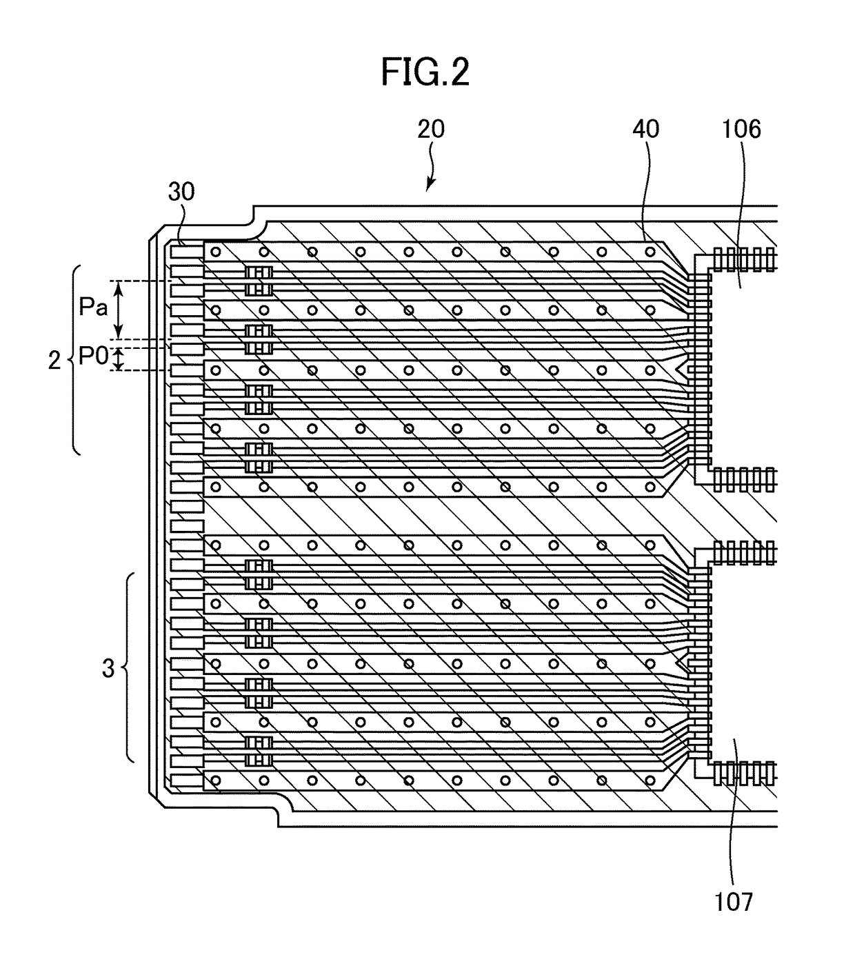
[0111]FIG. 20 is a top view of the printed circuit board 20 according to a third embodiment of the present invention. As compared to the printed circuit board 20 according to the first embodiment, the printed circuit board 20 according to this embodiment differs in the wiring layout and in that metal wiring 118 is arranged between the receiver-side differential transmission line 2 and the transmitter-side differential transmission line 3. However, other points are the same as those in the first embodiment. As illustrated in FIG. 20, the inner strip conductor pair, which is arranged at the innermost side in the strip conductor pairs 104 included in the receiver-side differential transmission line 2, is extended linearly from the via hole 109 to the via hole 119. Further, the transmitter-side differential transmission line 3 can also have a structure similar to the above-mentioned structure of the receiver-side differential transmission line 2. With this, the crosstalk amount between ...


PUM


Abstract

A differential transmission circuit includes: a dielectric layer for embedding a plurality of first strip conductor pairs arranged side by side in the same layer above a ground conductor layer, each of the plurality of first strip conductor pairs including a first right strip conductor and a first left strip conductor, the dielectric layer being formed from an upper side of the ground conductor layer up to a region above the plurality of first strip conductor pairs, the dielectric layer having a flat upper surface. A region between adjacent two of the plurality of first strip conductor pairs is embedded in the dielectric layer without arranging a conductor in the region.

Description

CROSS-REFERENCE TO RELATED APPLICATION[0001]The present application claims priority from Japanese application JP 2014-075627 filed on Apr. 1, 2014, the content of which is hereby incorporated by reference into this application.BACKGROUND OF THE INVENTION[0002]1. Field of the Invention[0003]The present invention relates to a differential transmission circuit, an optical module, and a method of manufacturing a differential transmission circuit.[0004]2. Description of the Related Art[0005]For example, optical modules (optical transceiver modules) for optical fiber transmission have been increased in speed and reduced in size and cost along with the widespread use of broadband networks in recent years. In general, a differential transmission is used for high-speed digital signal transmission. Thus, on one surface of a printed circuit board of the optical module, a plurality of channels are formed of differential transmission lines (balanced transmission lines) for high-speed digital sig...

Claims


Application Information

Patent Timeline
Patent Type & Authority Patents(United States)
IPC IPC(8): H05K1/02H04B10/40H05K3/46G02B6/42H01P3/02H05K3/10
CPCH05K1/0245G02B6/4201H05K1/0298H05K2201/10121G02B6/428
Inventor KAGAYA, OSAMUTAKAHASHI, KOYU
Owner LUMENTUM JAPAN INC
Why Eureka
Try Eureka