Optical sensor

a technology of optical sensors and optical beams, applied in the field of optical beams, to achieve the effect of lowering the stray light level

Active Publication Date: 2015-07-30
MURATA MFG CO LTD
View PDF8 Cites 24 Cited by
  • Summary
  • Abstract
  • Description
  • Claims
  • Application Information

AI Technical Summary

Benefits of technology

[0007]The present invention has been conceived in view of the above problems, and an object of the invention is to provide optical sensors capable of miniaturization while reducing stray light.
[0009]According to the present invention, the optical axis of light outputted via the refractive-index medium is set at an elevation angle in a range of 47 degrees to 89 degrees toward the opposite direction side with respect to the light-receiving element, and the beam divergence angle is set to be in a range of 1.8 degrees to 42 degrees. As such, a stray light level can be lowered and a signal to noise ratio (S / N ratio) can be improved. Therefore, it is unnecessary to provide an optical barrier or the like, whereby the sensor can be miniaturized. In addition, also in the case where the upper side of the light-emitting element, the light-receiving element, and the like is covered with a light-transmissive cover, a variation of the stray light level can be made smaller at the positions in the upper-lower direction of the cover.
[0011]According to the present invention, the optical axis of light outputted via the lens is set at an elevation angle in a range of 50 degrees to 89 degrees toward the opposite direction side with respect to the light-receiving element, and the beam divergence angle is set to be in a range of 1.8 degrees to 20.3 degrees. This makes it possible to lower a stray light level. Further, since the light outputted from the light-emitting element is focused by the lens, the beam divergence angle can be made smaller, thereby making it possible to further reduce the influence of the stray light.
[0015]According to the present invention, the optical axis of light outputted via the slope member is set at an elevation angle in a range of 47 degrees to 57 degrees toward the opposite direction side with respect to the light-receiving element, and the beam divergence angle is set to be in a range of 29 degrees to 42 degrees. This makes it possible to lower the stray light level.
[0017]According to the present invention, the optical axis of light outputted via the refractive-index medium is set at an elevation angle in a range of 47 degrees to 89 degrees toward the opposite direction side with respect to the light-receiving elements, and the beam divergence angle is set to be in a range of 1.8 degrees to 42 degrees. This makes it possible to lower the stray light level. In addition, since the plurality of light-receiving elements are provided, not only the presence of a detection target object but also a moving direction thereof can be detected at the same time.

Problems solved by technology

Therefore, it is unnecessary to provide an optical barrier or the like, whereby the sensor can be miniaturized.

Method used


Image

  • Optical sensor
  • Optical sensor
  • Optical sensor

Examples


first embodiment

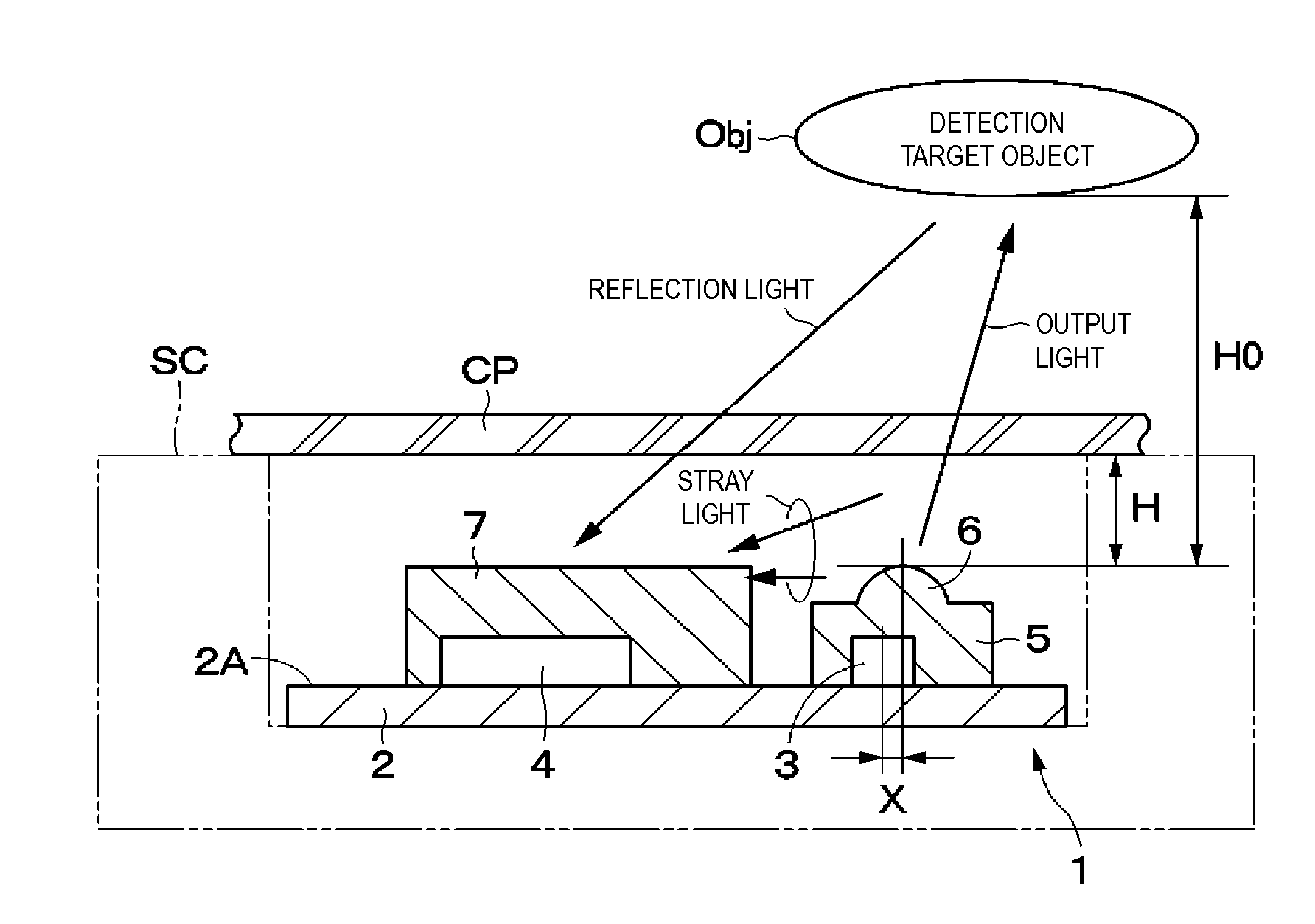
[0037]An optical sensor 1 is shown in FIGS. 1 through 3. The optical sensor 1 includes a substrate 2, a light-emitting element 3, a light-receiving element 4, a lens 6, and so on.

[0038]The substrate 2 is a plate formed of an insulating material. As the substrate 2, a printed circuit board is used, for example. On a surface 2A of the substrate 2, the light-emitting element 3 and the light-receiving element 4 are mounted.

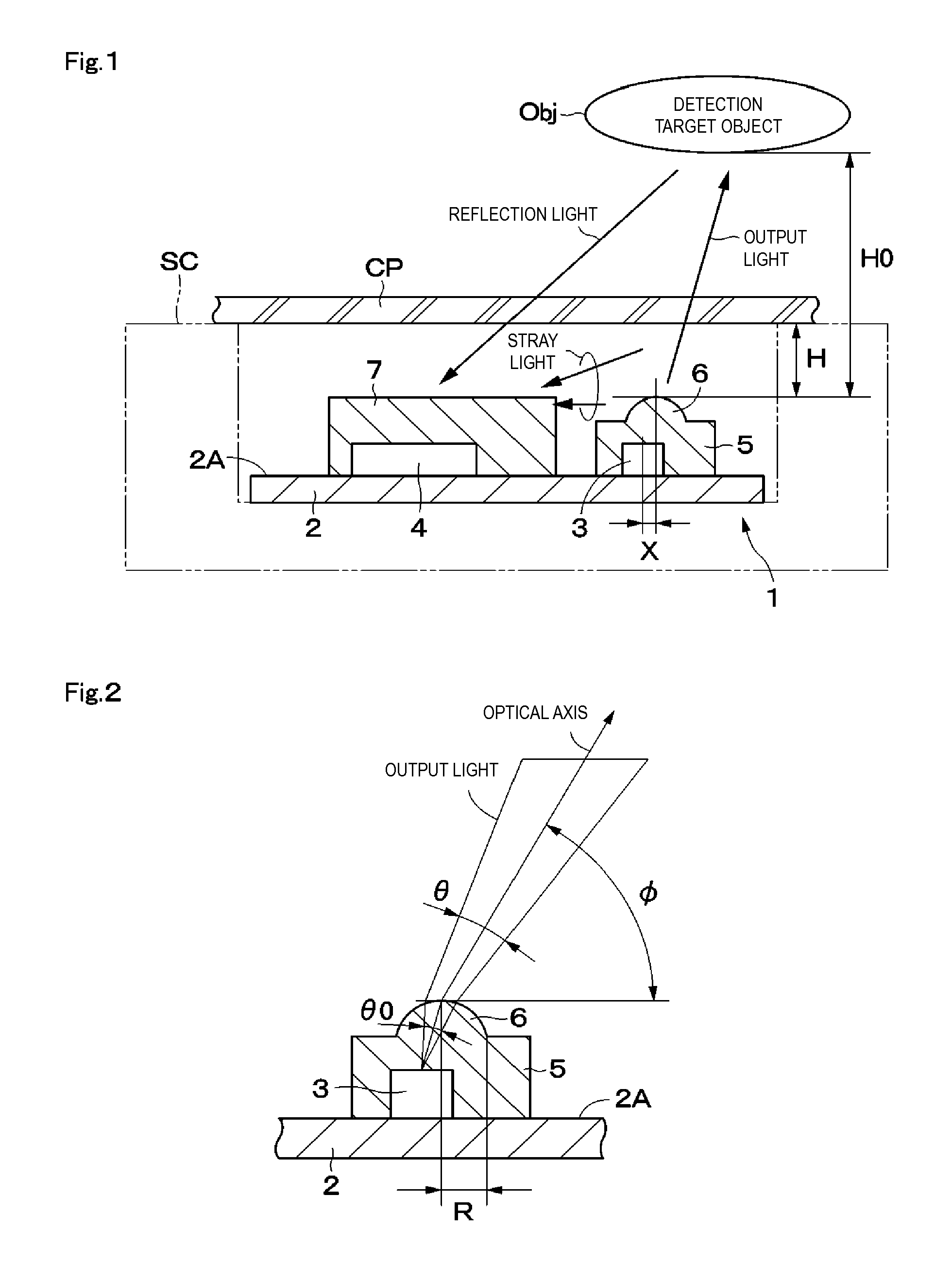
[0039]The light-emitting element 3 is mounted on the surface 2A of the substrate 2, and outputs light such as infrared light, visible light, or the like. An optical axis of the light-emitting element 3 normally extends in a direction perpendicular to the surface 2A of the substrate 2 (Z axis direction), for example. As the light-emitting element 3, a light-emitting diode (LED), a laser diode (LD), or a vertical cavity surface emitting laser (VCSEL) is used, for example. In order to increase the resolution of detection and improve the S / N ratio, it is preferable to us...

third embodiment

[0082]In an optical sensor 31 two light-receiving elements 32 and 33 are mounted on the substrate 2, and these two light-receiving elements 32 and 33 are sealed by, for example, a transparent resin member 34. Lenses respectively configured to focus light on the light-receiving elements 32 and 33 may be provided in the transparent resin member 34.

[0083]The two light-receiving elements 32 and 33 are disposed at positions that do not sandwich the light-emitting element 3. For example, the light-emitting element 3 is disposed on the right side in FIG. 18, while both the light-receiving elements 32 and 33 are disposed on the left side in FIG. 18.

[0084]Meanwhile, the light-receiving element 32 and light-receiving element 33 are disposed at different positions in the upper-lower direction in FIG. 18. As such, when the detection target object Obj moving in the upper-lower direction in FIG. 18 passes over the optical sensor 31, light that is outputted from the light-emitting element 3 strik...


PUM


Abstract

A light-emitting element and a light-receiving element are provided on a surface of a substrate. The light-emitting element and the light-receiving element are sealed by transparent resin members and, respectively. A lens is provided at the transparent resin member at a position above the light-emitting element. The center of the lens and a mounting position of the light-emitting element are disposed being shifted from each other. With this, an optical axis of light outputted via the lens is slanted toward an opposite direction side with respect to the light-receiving element at a predetermined elevation angle. In this case, a beam divergence angle of light outputted from the lens is set to a predetermined value.

Description

CROSS REFERENCE TO RELATED APPLICATIONS[0001]The present application is a continuation of PCT / JP2013 / 075146 filed Sep. 18, 2013, which claims priority to Japanese Patent Application No. 2012-223008, filed Oct. 5, 2012, the entire contents of each of which are incorporated herein by reference.FIELD OF THE INVENTION[0002]The present invention relates to optical sensors configured to detect presence of detection target objects using light-emitting elements and light-receiving elements.BACKGROUND OF THE INVENTION[0003]In general, optical sensors configured to detect presence of detection target objects such as fingers, hands, and the like using light-emitting elements and light-receiving elements are known (for example, see Patent Document 1). The known optical sensor detects the presence of a detection target object in the following manner: that is, light is outputted from a light-emitting element and reflected by the detection target object, and the reflected light is then received by...

Claims


Application Information

Patent Timeline
Patent Type & Authority Applications(United States)
IPC IPC(8): G01S17/02G01S7/481G01S17/04
CPCG01S7/4814G01S17/026G01S7/4813G01S7/4816H01L31/0203H01L31/02327H01L31/173G01S17/04Y02E10/52H01L2924/1815
Inventor HANADA, KANAMECHIKU, SHINICHIROYAMASAKI, TSUTOMUSONODA, TOMIYA
Owner MURATA MFG CO LTD
Why Eureka
Try Eureka