Photographing optical lens assembly, image capturing apparatus and electronic device

a technology of optical lens and image capturing apparatus, applied in the direction of optics, optical elements, instruments, etc., can solve the problems of diverse and strict specifications of photographing modules in response to market demands

Active Publication Date: 2018-03-01
LARGAN PRECISION
View PDF9 Cites 24 Cited by
  • Summary
  • Abstract
  • Description
  • Claims
  • Application Information

AI Technical Summary

Benefits of technology

[0081]The photographing optical lens assembly can further include an aperture stop which can be located between an imaged object and the first lens element. Therefore, the telecentric effect can be obtained by adjusting the location of the aperture stop, so that the image-receiving efficiency of the image sensor can be increased.
[0069]When the focal length of the first lens element is f1, and a focal length of the fourth lens element is f4, the following condition is satisfied: 0<|f1 / f4|<0.90. Therefore, it is favorable for moderating the variation of the light after incident into the photographing optical lens assembly by adjusting the distribution of the refractive power of the first lens element and the fourth lens element so as to reduce the stray light thereof. Preferably, the following condition can be satisfied: 0<|f1 / f4|<0.75.
[0070]When a curvature radius of the object-side surface of the second lens element is R3, and a curvature radius of an image-side surface of the second lens element is R4, the following condition is satisfied: −10.0<(R3+R4) / (R3−R4)<0.20. Therefore, it is favorable for correcting aberrations of the photographing optical lens assembly effectively by controlling the distribution of io surface curvatures of the second lens element so as to enhance image quality. Preferably, the following condition can be satisfied: −5.0<(R3+R4) / (R3−R4)<0.
[0054]FIG. 37 is a schematic view of parameter Yc41, Yc42, Yc51 and Yc52 of the photographing optical lens assembly of FIG. 1; and
[0078]When an axial distance between an object-side surface of the first lens element and the image-side surface of the fifth lens element is TD, and the central thickness of the second lens element is CT2, the following condition is satisfied: 1.20<TD / CT2<7.50. Therefore, the proportion of the thickness of the second lens element in the photographing optical lens assembly can be controlled, so that the negative refractive power of the second lens element can be strengthened for enhancing the telephoto characteristic thereof. Preferably, the following condition can be satisfied: 1.20<TD / CT2<6.0.

Problems solved by technology

Thus, specifications of photographing modules in response to market demands are becoming diverse and strict.
In conventional telephoto lens assemblies with smaller field of view, the volume thereof is hard to reduce due to restrictions of shape of lens surface and variations of lens material, and it cannot be balanced among molding of lens elements, assembling convenience and system sensitivity.

Method used


Image

  • Photographing optical lens assembly, image capturing apparatus and electronic device
  • Photographing optical lens assembly, image capturing apparatus and electronic device
  • Photographing optical lens assembly, image capturing apparatus and electronic device

Examples


1st embodiment

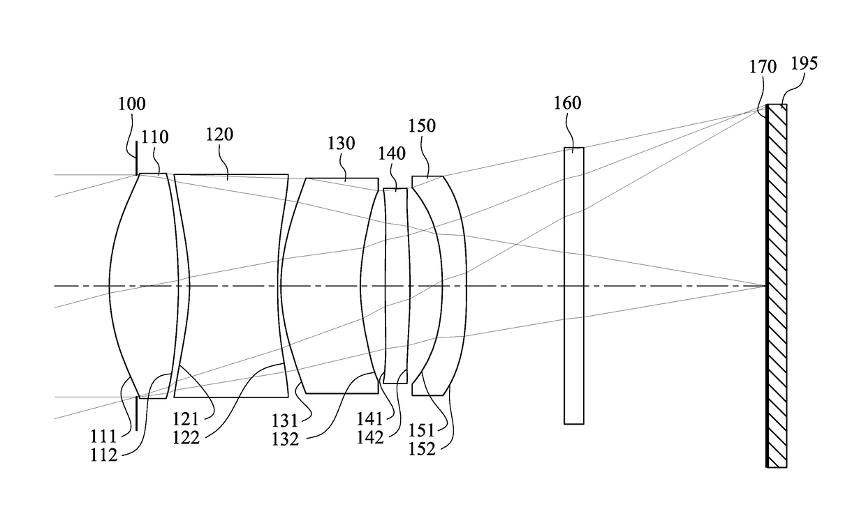
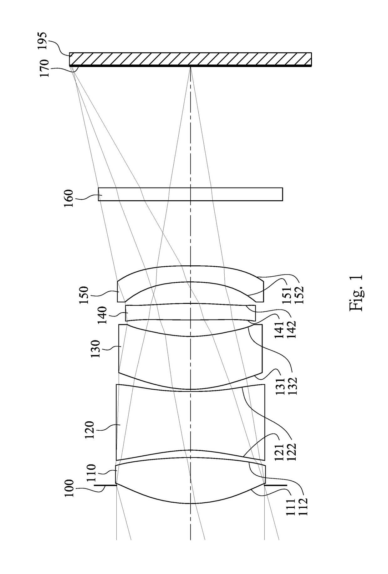
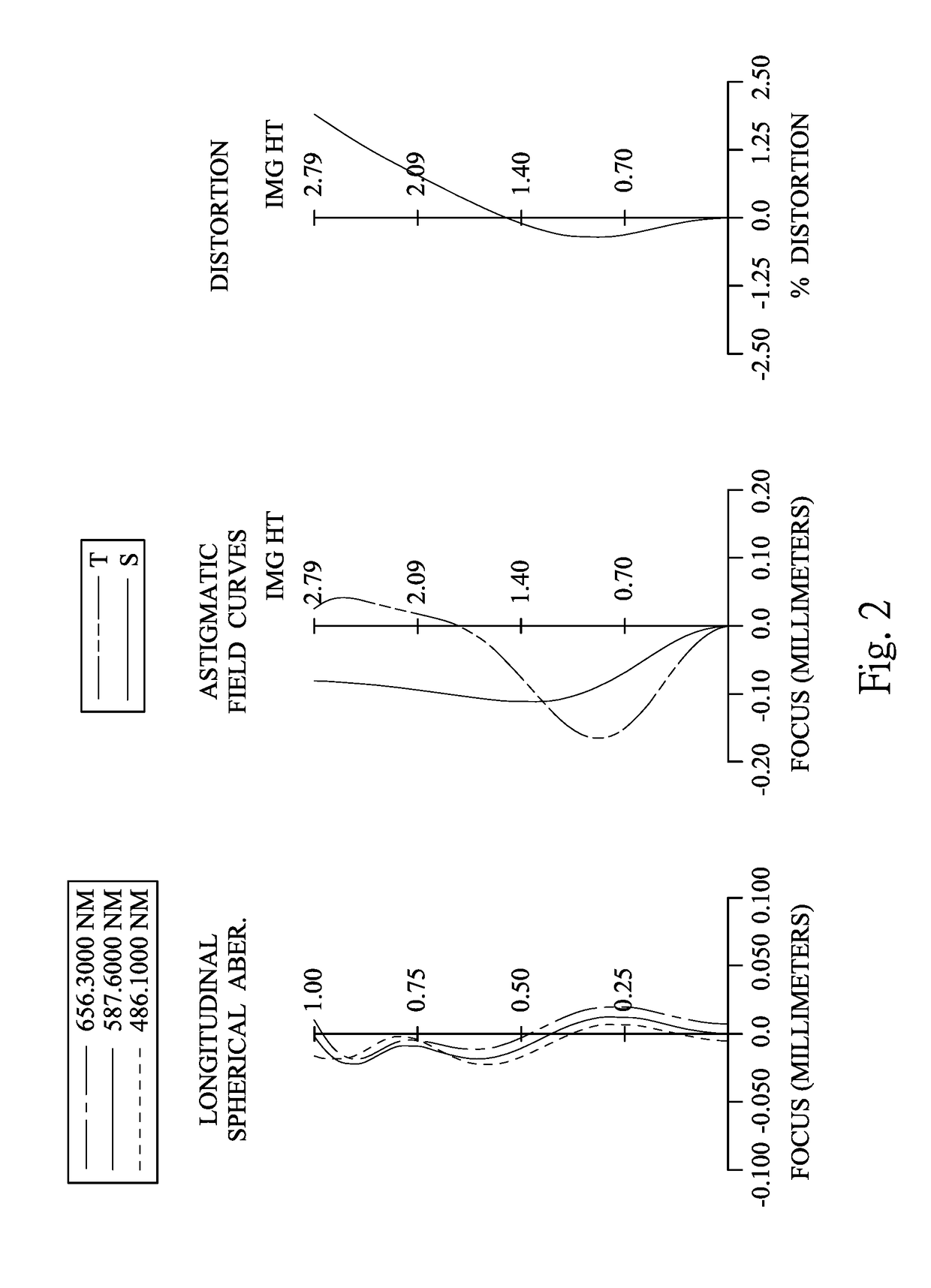
[0092]FIG. 1 is a schematic view of an image capturing apparatus according to the 1st embodiment of the present disclosure. FIG. 2 shows spherical aberration curves, astigmatic field curves and a distortion curve of the image capturing apparatus according to the 1st embodiment. In FIG. 1, the image capturing apparatus includes a photographing optical lens assembly (its reference numeral is omitted) and an image sensor 195. The photographing optical lens assembly includes, in order from an object side to an image side along an optical axis, an aperture stop 100, a first lens element 110, a second lens element 120, a third lens element 130, a fourth lens element 140, a fifth lens element 150, a filter 160 and an image surface 170, wherein the image sensor 195 is disposed on the image surface 170 of the photographing optical lens assembly. The photographing optical lens assembly has a total of five lens elements (110-150), and there is an air space between every two lens elements of th...

2nd embodiment

[0121]FIG. 3 is a schematic view of an image capturing apparatus according to the 2nd embodiment of the present disclosure. FIG. 4 shows spherical aberration curves, astigmatic field curves and a distortion curve of the image capturing apparatus according to the 2nd embodiment. In FIG. 3, the image capturing apparatus includes a photographing optical lens assembly (its reference numeral is omitted) and an image sensor 295. The photographing optical lens assembly includes, in order from an object side to an image side along an optical axis, an aperture stop 200, a first lens element 210, a second lens element 220, a third lens element 230, a fourth lens element 240, a fifth lens element 250, a filter 260 and an image surface 270, wherein the image sensor 295 is disposed on the image surface 270 of the photographing optical lens assembly. The photographing optical lens assembly has a total of five lens elements (210-250), and there is an air space between every two lens elements of th...

3rd embodiment

[0133]FIG. 5 is a schematic view of an image capturing apparatus according to the 3rd embodiment of the present disclosure. FIG. 6 shows spherical aberration curves, astigmatic field curves and a distortion curve of the image capturing apparatus according to the 3rd embodiment. In FIG. 5, the image to capturing apparatus includes a photographing optical lens assembly (its reference numeral is omitted) and an image sensor 395. The photographing optical lens assembly includes, in order from an object side to an image side along an optical axis, a first lens element 310, an aperture stop 300, a second lens element 320, a third lens element 330, a fourth lens element 340, a fifth lens element 350, a filter 360 and an image surface 370, wherein the image sensor 395 is disposed on the image surface 370 of the photographing optical lens assembly. The photographing optical lens assembly has a total of five lens elements (310-350), and there is an air space between every two lens elements of...


PUM


Abstract

A photographing optical lens assembly includes, in order from an object side to an image side along an optical axis, a first lens element, a second lens element, a third lens element, a fourth lens element and a fifth lens element. The first lens element has positive refractive power. The second lens element has negative refractive power. The third lens element has an object-side surface being convex in a paraxial region thereof.

Description

RELATED APPLICATIONS[0001]This application claims priority to U.S. Provisional Application Ser. No. 62 / 378,296, filed Aug. 23, 2016, which is herein incorporated by reference,BACKGROUNDTechnical Field[0002]The present disclosure relates to a photographing optical lens assembly and an image capturing apparatus. More particularly, the present disclosure relates to a photographing optical lens assembly and an image capturing apparatus with a compact size applicable to electronic devices.Description of Related Art[0003]With the popularity of photographing module applications, photographing modules can be utilized in electronic devices, such as various intelligent electronic devices, wearable devices, digital cameras, multiple lens devices, surveillance systems, driving recording systems, rearview camera systems and human-computer Interaction platform, etc. Thus, specifications of photographing modules in response to market demands are becoming diverse and strict.[0004]In conventional te...

Claims


Application Information

Patent Timeline
Patent Type & Authority Applications(United States)
IPC IPC(8): G02B13/00G02B13/02G02B5/00G02B27/00
CPCG02B13/0045G02B27/0025G02B5/00G02B13/02G02B13/0015G02B13/0065
Inventor LIN, CHENG-CHENHUANG, HSIN-HSUANYANG, SHU-YUN
Owner LARGAN PRECISION
Why Eureka
Try Eureka