

Revision glenoid device and method
a glenoid and component technology, applied in the field of orthopaedics, can solve the problems of increasing the pain of an individual, limiting the range of motion of the patient's shoulder joint, and severe shoulder pain
- Summary
- Abstract
- Description
- Claims
- Application Information
AI Technical Summary
Benefits of technology
Problems solved by technology
Method used
Image

Examples
Embodiment Construction
[0033]Like reference numerals refer to like parts throughout the following description and the accompanying drawings.
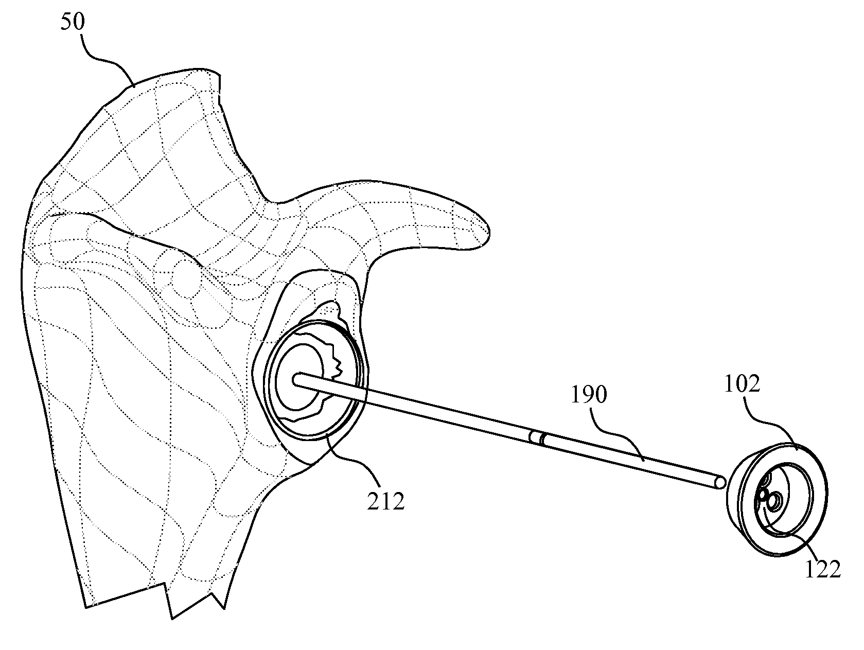
[0034]FIG. 3 depicts a retroversion glenoid component 100. The glenoid component 100 includes a base component 102 and an articulation component 104. With further reference to FIGS. 4-6, the base component 102 includes a wall 106 which extends between a lip 108 and a bottom surface 110. At the lip 108, the wall106 defines a circular outer periphery that is slightly larger than the circular outer periphery of the wall 106 at the bottom surface 110.
[0035]The lip 108 defines a receptacle 112 which is substantially cylindrical. The receptacle 112 extends from the lip 108 to a lower surface 114. Three fastener holes 116, 118, and 120 extend through the lower surface 114 and the bottom surface 110. A guide hole 122 also extends through the lower surface 114 and the bottom surface 110. The guide hole 122 and the receptacle 112 are centrally located. Accordingly, the guide ho...
PUM
 Abstract
Description
Claims
Application Information