
Patient lift and coupling therefor

Inactive Publication Date: 2012-09-27
ARJO IP HLDG AB
View PDF13 Cites 2 Cited by
  • Summary
  • Abstract
  • Description
  • Claims
  • Application Information

AI Technical Summary

Benefits of technology

[0009]According to an aspect of the present invention, there is provided a patient lift composing a boom, a spreader bar characterised in that a friction coupling releasably attaches the boom and spreader bar. The friction coupling restricts the movement of the spreader bar and eliminates the risk of the spreader bar swinging against the patient's face. Furthermore, the friction reduces the swing of the patient when transferred in the lift. This makes the lift easier to manoeuvre for the caregiver.

Problems solved by technology

Furthermore, the friction reduces the swing of the patient when transferred in the lift.

Method used


Image

  • Patient lift and coupling therefor
  • Patient lift and coupling therefor
  • Patient lift and coupling therefor

Examples


Embodiment Construction

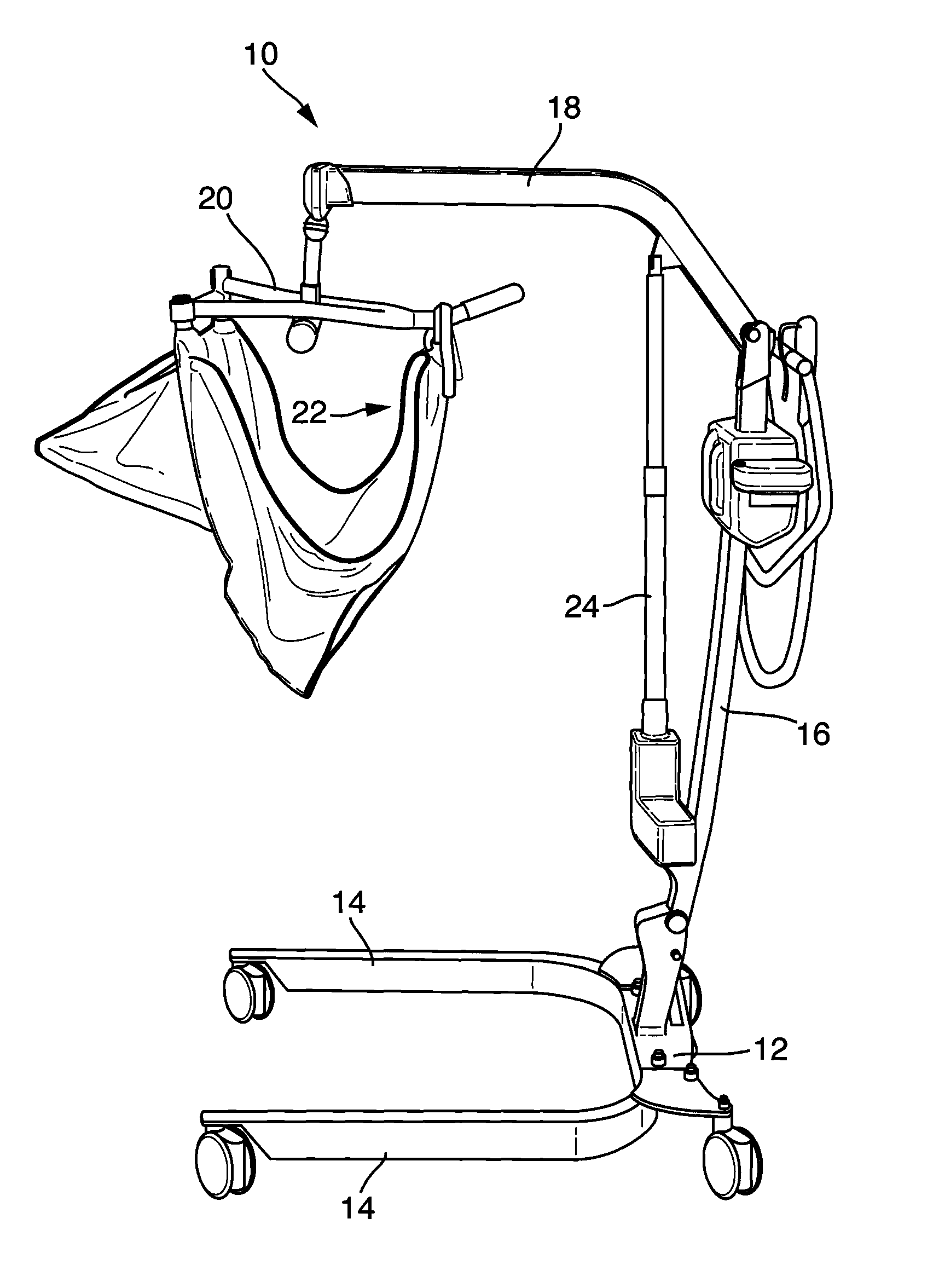
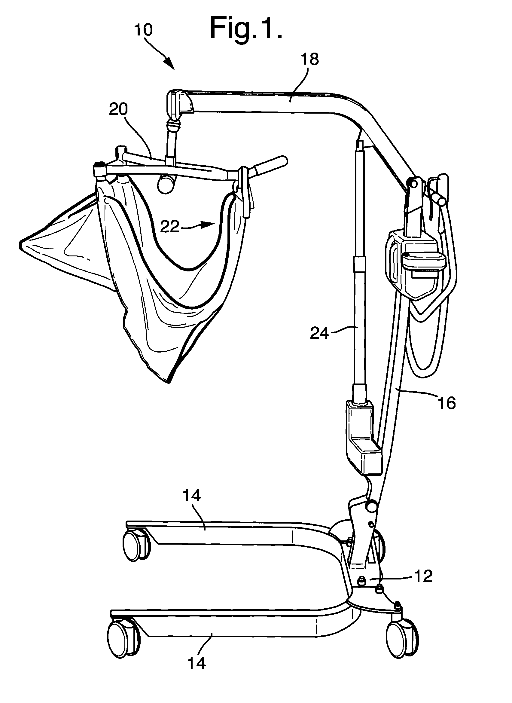
[0029]Referring first to FIG. 1, there is shown an example of arc-type patient lift 10. The lift 10 includes a base 12 conventionally provided with two legs 14 and a mast 16 extending from the base 12. The mast couples to a boom 18, which in turn is coupled to a spreader bar 20 to which a sling 22 or other patient support is coupled. A piston drive arrangement 24 is provided for raising and lowering the boom 18 and thus the sling 22. The patient lift 10 allows for the boom to be swung by a care worker in order to move the sling 22 so as to prepare for or to move a patient.

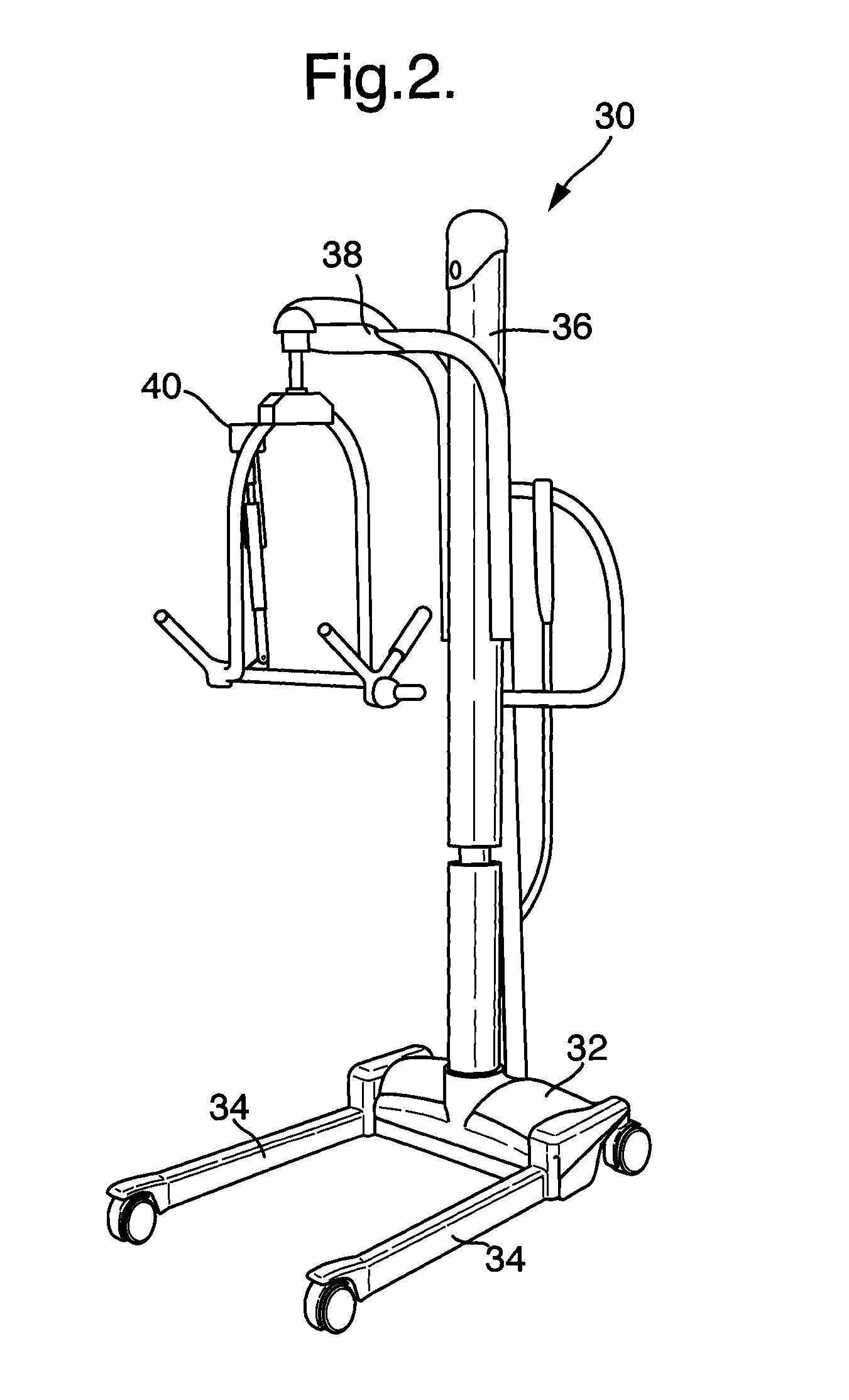
[0030]FIG. 2 shows an example of a column-type patient lift 30, which is similarly provided with a base 32 having legs 34. The mast 36 extends vertically from the base 32 and in this example incorporates the piston lift arrangement for raising and lowering the mast. A boom 38 extends from the mast and at an end of this there is provided a spreader bar 40 which can support a sling or other coupling arrangement (not ...


PUM


Abstract

A patient lift including a boom a spreader bar, and a friction coupling for securing the boom and the spreader bar. The friction coupling may include two friction washers disposed against respective inner faces of the boom. Two compression springs are disposed abutting the friction washers with a spreader bar support member in between. The compression springs urge the friction washers against the inner faces of the boom end. The spreader bar does not swing when the lift is moved without load. Also, the friction coupling reduces the swing of the patient, when transferred in the lift. This makes the lift easier to manoeuvre for the caregiver.

Description

CROSS-REFERENCE TO RELATED APPLICATIONS[0001]This application is a non-provisional application which claims priority to European Patent Application Nos. EP09171280.2 filed Sep. 24, 2009; EP10165718.7 filed Jun. 11, 2010; and PCT Application No. PCT / EP2010 / 063856 filed Sep. 21, 2010, each of which is incorporated by reference herein in its entirety.TECHNICAL FIELD[0002]The present invention relates to a lift device, a coupling therefor and more particularly, to a structure for attaching a spreader bar to patient lifts.BACKGROUND[0003]Patient lifts are generally known in the health care industry. Such patient lifts help a caregiver to transfer a patient from one place to another such as bed to chair, toilet, stretcher, and so on.[0004]There are primarily two types of such patient lifts, arc lifts and column lifts. Examples of these are shown in FIGS. 1 and 2 respectively. These lifts typically include a support arm or boom and a spreader bar or cradle supported by the boom. A sling fo...

Claims


Application Information

Patent Timeline
IPC IPC(8): A61G7/10
CPCA61G7/1017A61G2200/34A61G7/1061
Inventor NIKLASSON, THERESE
Owner ARJO IP HLDG AB
Features
  • Generate Ideas
  • Intellectual Property
  • Life Sciences
  • Materials
  • Tech Scout
  • Unparalleled Data Quality
  • Higher Quality Content
  • 60% Fewer Hallucinations
Learn More