
Mist cooling apparatus, heat treatment apparatus, and mist cooling method

Active Publication Date: 2012-09-27
IHI CORP +1
View PDF5 Cites 3 Cited by
  • Summary
  • Abstract
  • Description
  • Claims
  • Application Information

AI Technical Summary

Benefits of technology

[0017]According to the invention, it is possible to obtain the following effects.
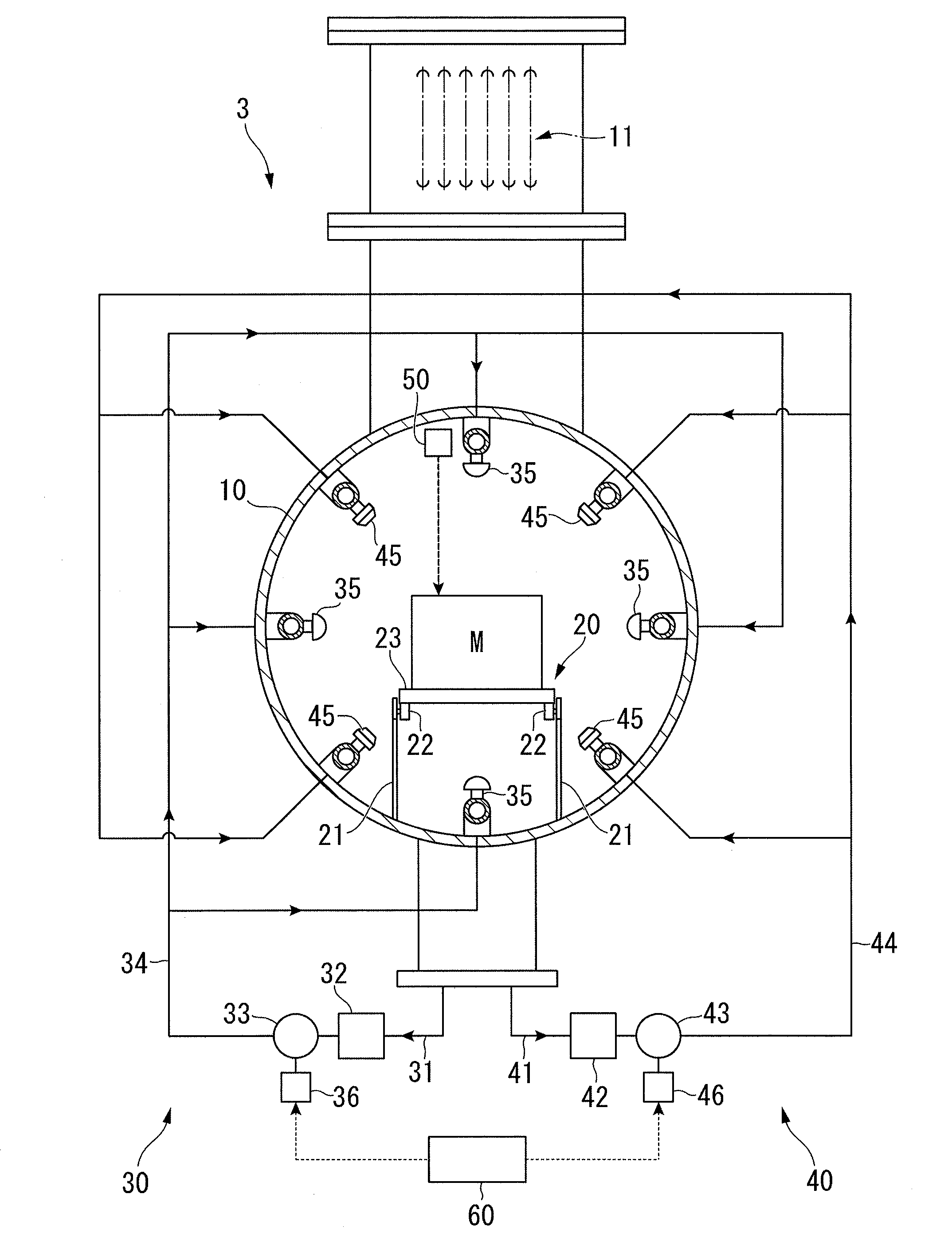
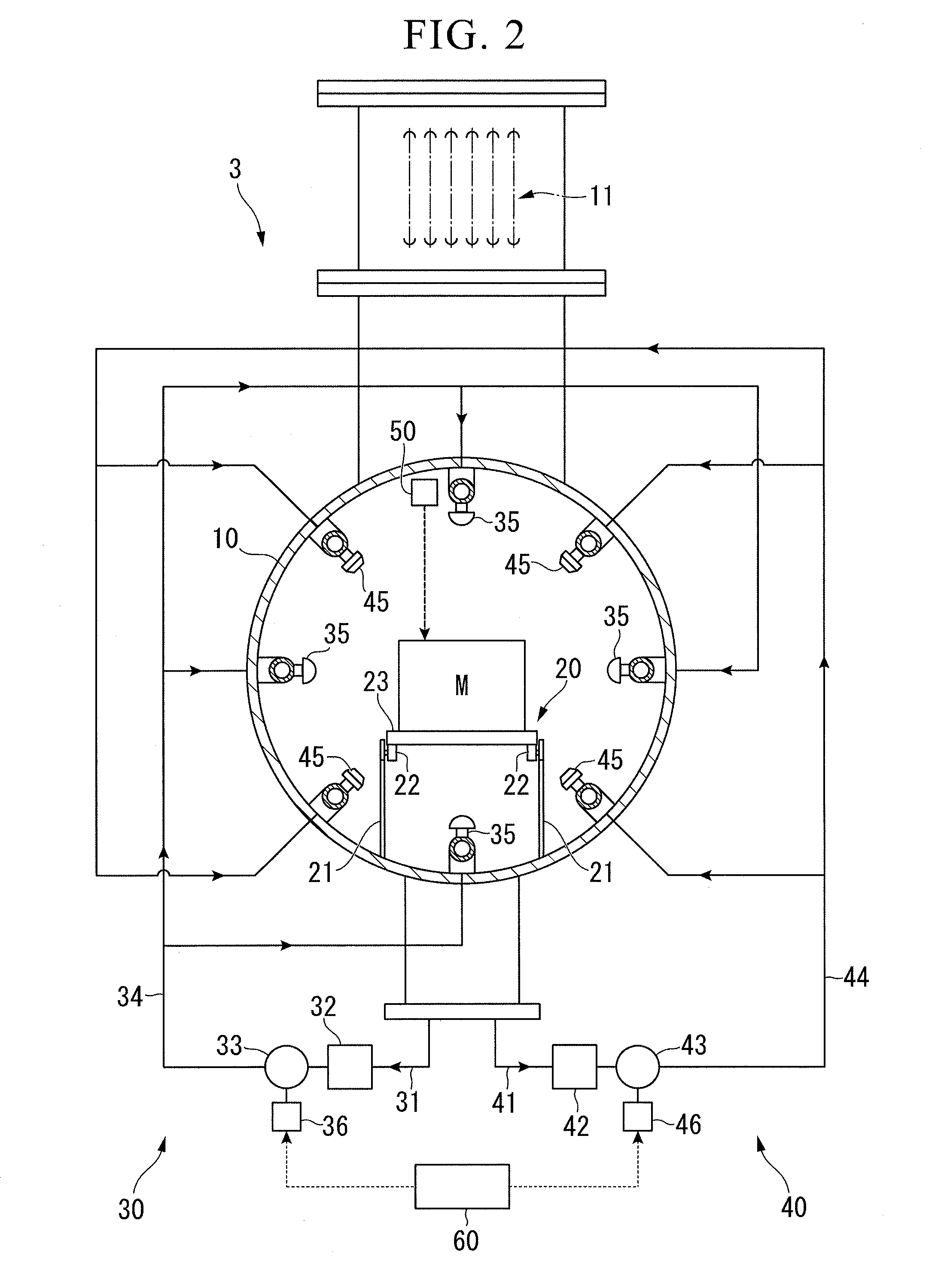
[0018]The invention includes the first nozzle which is used for the rapid cooling and the second nozzle which is used for the gentle cooling with maintaining the uniformity of cooling. For this reason, it is possible to cool the treated subject of the heat treatment at a wide range of cooling speeds. Further, the rapid cooling is performed during a certain period and the gentle cooling may be performed with the uniformity of cooling during the other period so as to prevent deformation or warpage of the treated subject.

Problems solved by technology

Further, when the mist ejection amount or the mist ejection time is adjusted, the mist cooling apparatus may easily control cooling speed of the treated subject which is difficult to control in an immersion type cooling apparatus of the related art.

Method used


Image

  • Mist cooling apparatus, heat treatment apparatus, and mist cooling method
  • Mist cooling apparatus, heat treatment apparatus, and mist cooling method
  • Mist cooling apparatus, heat treatment apparatus, and mist cooling method

Examples


Embodiment Construction

[0027]Hereinafter, an embodiment of the invention will be described by referring to FIGS. 1 to 5C. Furthermore, in the drawings used in the following description, the scales of the members are appropriately changed so that the respective members are changed into recognizable sizes. Further, in the following description, a two-chamber-type heat treatment apparatus will be exemplified as a heat treatment apparatus.

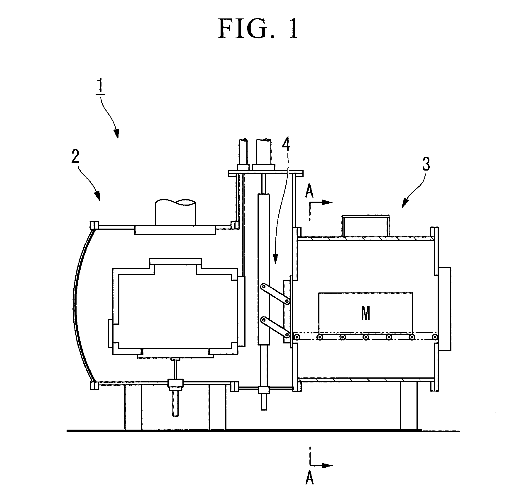
[0028]FIG. 1 is an overall configuration diagram illustrating a heat treatment apparatus 1 according to the present embodiment.

[0029]The heat treatment apparatus 1 is an apparatus which performs a heat treatment such as quenching on a treated subject M. The heat treatment apparatus 1 includes a heating chamber 2 and a cooling chamber (mist cooling apparatus) 3. The heating chamber 2 and the cooling chamber 3 are disposed so as to be adjacent to each other. A partition wall 4 which is openable and closable is provided between the heating chamber 2 and the cooling chamber 3. A...


PUM

PropertyMeasurementUnit
Angleaaaaaaaaaa
Particle diameteraaaaaaaaaa

Abstract

The invention adopts a mist cooling apparatus (3) that cools a heated treated subject M by spraying a cooling mist thereto, the mist cooling apparatus including: a first nozzle (35) that sprays a cooling mist; and a second nozzle (45) that sprays a cooling mist having a particle diameter smaller than the particle diameter of the cooling mist sprayed from the first nozzle.

Description

TECHNICAL FIELD[0001]The present invention relates to a mist cooling apparatus, a heat treatment apparatus, and a mist cooling method.[0002]Priority is claimed on Japanese Patent Application No. 2009-281595, filed Dec. 11, 2009, the content of which is incorporated herein by reference.BACKGROUND ART[0003]Patent Document 1 discloses a mist cooling apparatus which is used for the heat treatment on a treated subject such as metal so as to cool the treated subject. The mist cooling apparatus sprays a mist-like cooling liquid to the heated treated subject so as to cool the treated subject using the latent heat of vaporization of the cooling liquid. For this reason, the mist cooling apparatus has high cooling performance compared to a gas ejecting type cooling apparatus of the related art. Further, when the mist ejection amount or the mist ejection time is adjusted, the mist cooling apparatus may easily control cooling speed of the treated subject which is difficult to control in an immer...

Claims


Application Information

Patent Timeline
IPC IPC(8): C21D11/00C21D1/667
CPCC21D1/00C21D1/667C21D1/62F27D7/02F27D15/02F27D2009/0005F27D2009/0072
Inventor KATSUMATA, KAZUHIKOUEDA, AMIKUDO, SHINYASHIMADA, TAKAHISA
Owner IHI CORP
Learn More