
Image forming apparatus, display method, and non-transitory computer-readable recording medium encoded with display program

a display program and image forming technology, applied in the field of image forming apparatus, display method, non-transitory computer-readable recording medium encoded with display program, can solve the problems of increasing complexity of multi-function peripheral functions and difficulty in identifying respective keys on the keyboard

Inactive Publication Date: 2012-09-27
KONICA MINOLTA INC
View PDF12 Cites 11 Cited by
  • Summary
  • Abstract
  • Description
  • Claims
  • Application Information

AI Technical Summary

Benefits of technology

[0003]The present invention relates to an image forming apparatus, a display method, and a non-transitory computer-readable recording medium encoded with a display program. More particularly, the present invention relates to an image forming apparatus which performs processing in accordance with setting values, a display method executed by the image forming apparatus, and a non-transitory computer-readable recording medium encoded with a display program for causing a computer to execute the display method.
[0003]The present invention relates to an image forming apparatus, a display method, and a non-transitory computer-readable recording medium encoded with a display program. More particularly, the present invention relates to an image forming apparatus which performs processing in accordance with setting values, a display method executed by the image forming apparatus, and a non-transitory computer-readable recording medium encoded with a display program for causing a computer to execute the display method.

Problems solved by technology

Recently, the functions included in a multi-function peripheral (MFP) have increased in complexity.
With a semitransparent software keyboard, however, it is difficult to identify respective keys in the keyboard.

Method used


Image

  • Image forming apparatus, display method, and non-transitory computer-readable recording medium encoded with display program
  • Image forming apparatus, display method, and non-transitory computer-readable recording medium encoded with display program
  • Image forming apparatus, display method, and non-transitory computer-readable recording medium encoded with display program

Examples


Embodiment Construction

[0021]The preferred embodiment of the present invention will be described below in conjunction with the drawings. In the following description, the same or corresponding parts are denoted by the same reference characters. Their names and functions are also the same. Thus, a detailed description thereof will not be repeated.

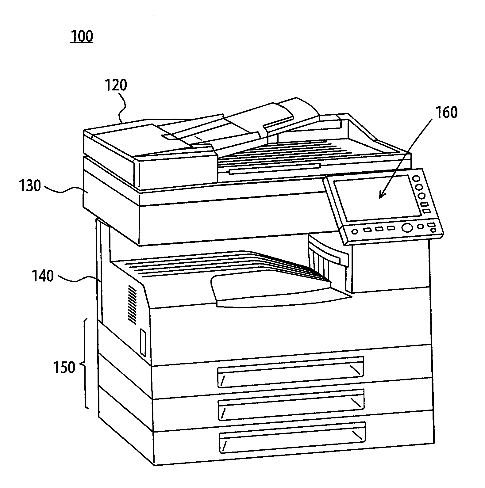
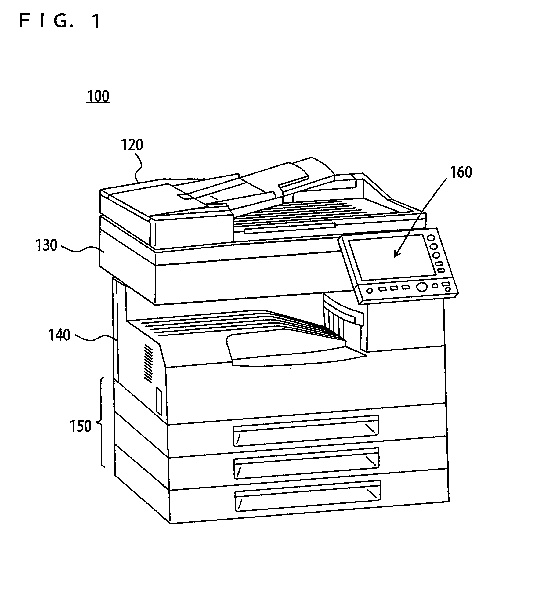
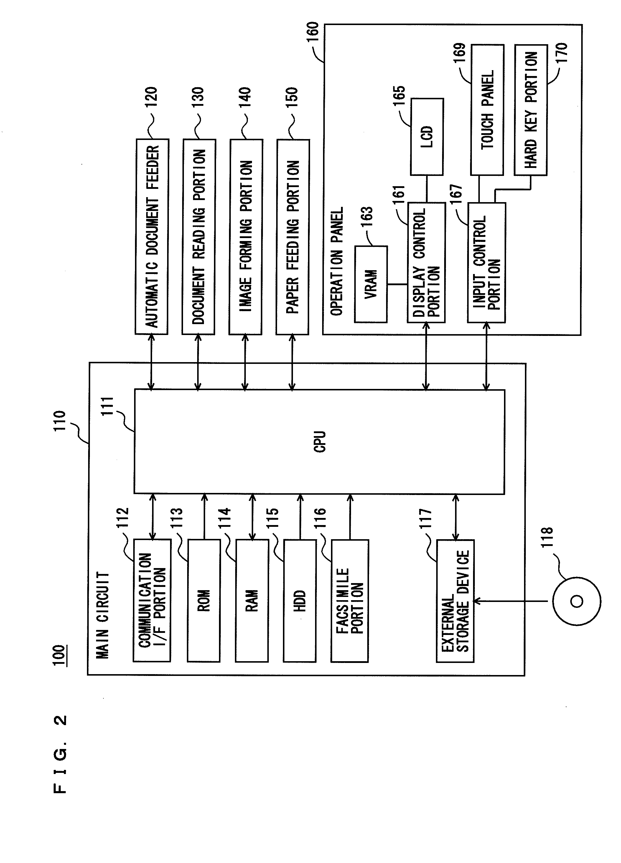
[0022]FIG. 1 is a perspective view of an MFP according to an embodiment of the present invention. FIG. 2 is a block diagram schematically showing the hardware configuration of the MFP. Referring to FIGS. 1 and 2, an MFP 100 serving as an image forming apparatus includes: a main circuit 110; a document reading portion 130 for reading a document; an automatic document feeder 120 for feeding a document to document reading portion 130; an image forming portion 140 for forming an image on a sheet of paper or the like on the basis of image data which is output from document reading portion 130 that has read a document; a paper feeding portion 150 for feeding a sheet of ...


PUM


Abstract

An image forming apparatus includes a position detecting portion to detect a position designated by a user on a display surface of a display portion, a first display controlling portion to cause the display portion to display a first screen, a position check image displaying portion, responsive to detection of a position within a designation button on the first screen, to cause the display portion to display a position check image identical in shape and size to a second screen, a moving portion to move the position check image in the first screen, a position finalizing portion to finalize a position for displaying the second screen on the basis of the position of the position check image in the first screen, and a second display controlling portion to cause the display portion to display the second screen at the finalized position, to be overlaid on the first screen.

Description

[0001]This application is based on Japanese Patent Application No. 2011-066330 filed with Japan Patent Office on Mar. 24, 2011, the entire content of which is hereby incorporated by reference.BACKGROUND OF THE INVENTION[0002]1. Field of the Invention[0003]The present invention relates to an image forming apparatus, a display method, and a non-transitory computer-readable recording medium encoded with a display program. More particularly, the present invention relates to an image forming apparatus which performs processing in accordance with setting values, a display method executed by the image forming apparatus, and a non-transitory computer-readable recording medium encoded with a display program for causing a computer to execute the display method.[0004]2. Description of the Related Art[0005]Recently, the functions included in a multi-function peripheral (MFP) have increased in complexity. In order to operate such an MFP, an increased number of items of processing conditions are ...

Claims


Application Information

Patent Timeline
IPC IPC(8): G09G5/00G06F3/048G06F3/0484G06F3/0486
CPCH04N1/00411H04N1/00424H04N1/00427H04N1/00472G06F3/04886H04N1/00482H04N1/00501H04N2201/0094H04N1/00474
Inventor TANAKA, YUSAKUKATO, TOMOKAZUKURUMASA, YOICHISUGIURATAMAI, YOSHIYUKI
Owner KONICA MINOLTA INC
Learn More