Contact-type step gauge probe detection pattern sample block

A probe detection and step meter technology, applied in the direction of instruments, measuring devices, etc., can solve the problems of wear, test result deviation, probe contamination, etc.

Active Publication Date: 2016-10-12
THE 13TH RES INST OF CHINA ELECTRONICS TECH GRP CORP
View PDF5 Cites 5 Cited by
  • Summary
  • Abstract
  • Description
  • Claims
  • Application Information

AI Technical Summary

Problems solved by technology

Usually, the step meter is calibrated by using the step meter template. The existing contact step meter template can only realize the measurement of the Z-axis performance of the step meter, and cannot realize the inspection of the probe performance and scanning position of the step meter. The contact step meter is used during the process The following problems often occur in the test: (1) The probe is contaminated or worn, causing the scanning pattern to be inconsistent with the actual properties of the device, making the measurement personnel mistakenly think that the device structure is two steps; (2) The scanning position is inaccurate, and the actual scanning position is different from the set The scan position does not match
Only when the scanning position inspection pattern is placed strictly horizontally can the verification result be accurate. Due to the small magnification of the step meter, it is difficult to observe whether the sample block is placed horizontally with the naked eye, which may easily lead to deviations in the detection results

Method used


Image

  • Contact-type step gauge probe detection pattern sample block
  • Contact-type step gauge probe detection pattern sample block
  • Contact-type step gauge probe detection pattern sample block

Examples


Embodiment Construction

[0022] The following will clearly and completely describe the technical solutions in the embodiments of the present invention with reference to the accompanying drawings in the embodiments of the present invention. Obviously, the described embodiments are only some, not all, embodiments of the present invention. Based on the embodiments of the present invention, any modifications, equivalent replacements and improvements within the spirit and principles of the present invention made by those of ordinary skill in the art without creative work fall within the protection scope of the present invention.

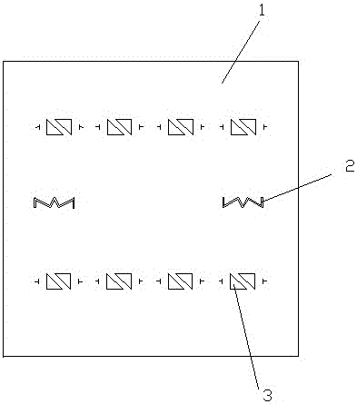
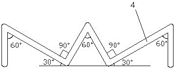
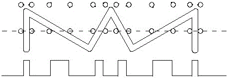
[0023] The contact profilometer probe detection pattern sample block includes a substrate 1, and the substrate 1 is provided with a probe performance inspection pattern 2 and / or a scanning position inspection pattern 3; the probe performance inspection pattern 2 is a plurality of convex tables Or groove-type step line segment 4, the horizontal scanning direction of the probe passe...


PUM


Abstract

The invention discloses a contact-type step gauge probe detection pattern sample block and relates to the technical field of step gauge measurement. The contact-type step gauge probe detection pattern sample block comprises probe performance check patterns and scanning position check patterns. The probe performance check patterns are designed in a W shape and an M shape, which are arranged in the left and right two scanning areas of the sample block respectively; W-shape and M-shape step structure lines form five angels of 30 DGC, 60 DGC, 90 DGC, 120 DGC and 150 DGC with the horizontal direction; and the probe performance check patterns can carry out performance detection on ten positions of a probe tip and judge whether the probe tip is worn or polluted. The scanning position check patterns are designed into two isosceles right triangles, of which the bevel edges are arranged oppositely in parallel; one right-angle edge of each isosceles right triangle is parallel to the horizontal direction; the two sides of each scanning position check pattern are respectively provided with a T-shaped line for indicating probe tip scanning position and direction; and the scanning position check patterns can judge whether the sample block is horizontally placed and probe scanning position is accurate. A probe can be calibrated in time, and measurement precision of a step gauge is improved.

Description

technical field [0001] The invention relates to the technical field of step meter measurement. Background technique [0002] At present, the semiconductor industry mainly uses a step meter to measure the step height, and the step measurement methods mainly include: contact measurement method and optical measurement method. The stylus is in contact with the surface of the sample during measurement, and the stylus can accurately reflect the shape change of the sample surface during the movement process, with high measurement accuracy, and has been widely used in the semiconductor industry. Usually, the step meter is calibrated by using the step meter template. The existing contact step meter template can only realize the measurement of the Z-axis performance of the step meter, and cannot realize the inspection of the probe performance and scanning position of the step meter. The contact step meter is used during the process The following problems often occur in the test: (1) ...

Claims


Application Information

Patent Timeline
Patent Type & Authority Applications(China)
IPC IPC(8): G01B21/08G01B21/20
CPCG01B21/042
Inventor 李锁印冯亚南韩志国赵琳许晓青吴爱华
Owner THE 13TH RES INST OF CHINA ELECTRONICS TECH GRP CORP
Why Eureka
Try Eureka