
Shift position switching controller

一种切换器、控制器的技术,应用在控制装置、传动装置控制、带有齿的元件等方向,能够解决响应劣化等问题

Active Publication Date: 2016-02-10
DENSO CORP
View PDF6 Cites 5 Cited by
  • Summary
  • Abstract
  • Description
  • Claims
  • Application Information

AI Technical Summary

Problems solved by technology

That is, the response of the gear shift to the R position deteriorates

Method used


Image

  • Shift position switching controller
  • Shift position switching controller
  • Shift position switching controller

Examples


Embodiment Construction

[0024] An example embodiment of the present invention is described below.

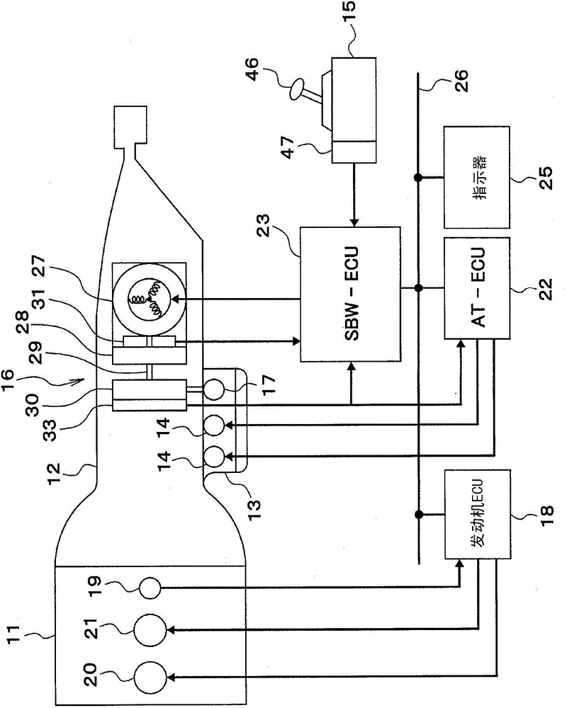
[0025] First, based on figure 1 Describe the outline configuration of an automatic transmission controller system in a vehicle.

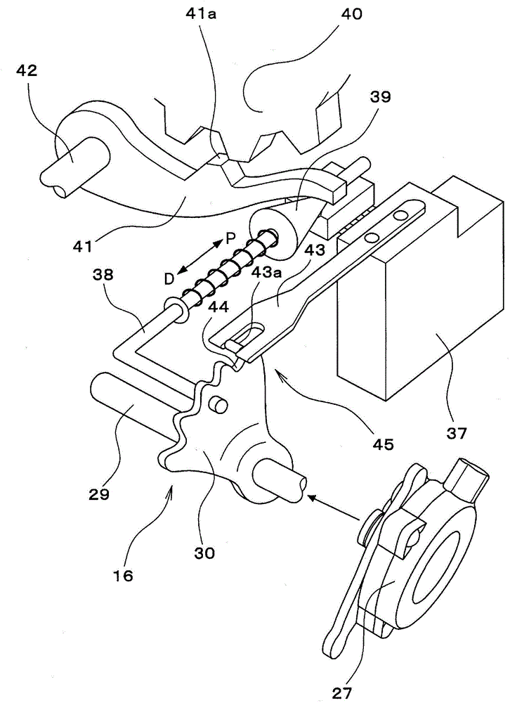
[0026] An input shaft of the automatic transmission 12 is connected to an output shaft (ie, a crankshaft) of the engine 11 . The automatic transmission 12 is provided with a transmission gear mechanism (not shown) and a hydraulic control circuit 13 . The transmission gear mechanism is provided with frictional engagement elements (not shown) such as a plurality of clutches and brakes for switching gear positions (ie, for switching gear ratios). Also, the hydraulic control circuit 13 is provided with an oil pressure control valve 14 that controls oil pressure applied to the frictional engagement elements and a manual valve 17 that switches the hydraulic fluid circuit of the frictional engagement elements. The manual valve 17 is driven by the position switching mechanism 16...


PUM


Abstract

A shift position switching controller determines whether the responsiveness for switching the shift position to an other-than-N position will be affected by a reduction of an N position check time and keeps the N position check time unchanged from a normal value if a current shift position is a D position or if a vehicle speed is equal to or greater than a preset value. Alternatively, the shift position switching controller determines whether the responsiveness of the controller will be affected by reducing the N position check time, and sets the N position check time to a shorter-than-normal value if the current shift position is a D position and the vehicle speed is equal to or greater than the preset value.

Description

technical field [0001] The present invention generally relates to a gear switching controller that uses a motor to switch gears. Background technique [0002] In recent years, mechanical drive systems in vehicles have been gradually replaced by electronic drive-by-wire systems in which components are driven by electric motors to improve space efficiency, assemblability, controllability, and the like. An example of this substitution can be found in a transmission range shifting mechanism. In such a system, when the target gear is changed according to the operation of a shift lever or the like, the gear is controlled to the target gear by rotating the motor to a target rotational position corresponding to the target gear. [0003] The gear shift controller disclosed in Patent Document 1 (ie, Japanese Patent Application No. JP2008-2561A) provides pre-fetch control. During gear shifting, when the shift control lever passes the N lever position, that is Say, at the moment when ...

Claims


Application Information

Patent Timeline
Patent Type & Authority Applications(China)
IPC IPC(8): F16H61/32B60K20/02
CPCF16H61/18F16H59/44F16H61/0213F16H2061/326F16H61/32B60K20/02
Inventor 川口优作吉田和弘
Owner DENSO CORP
Learn More