Operation panel device and image forming apparatus provided therewith

Inactive Publication Date: 2012-09-27
KONICA MINOLTA BUSINESS TECH INC
View PDF3 Cites 13 Cited by
  • Summary
  • Abstract
  • Description
  • Claims
  • Application Information

AI Technical Summary

Benefits of technology

[0011]The present invention is aimed to provide an operation panel device and an image forming apparatus, with which the operation panel device is compa

Problems solved by technology

Recently, the number of such operation keys disposed in the operation panel device is increased with the increasing number of functions of the image forming apparatus, and the operation panel device tends to become larger in size.
Disposition of the operation keys als

Method used


Image

  • Operation panel device and image forming apparatus provided therewith
  • Operation panel device and image forming apparatus provided therewith
  • Operation panel device and image forming apparatus provided therewith

Examples


Example

[0059]Hereinafter, an operation panel device according to an embodiment of the present invention and an image forming apparatus provided therewith will be described with reference to the drawings. In the following embodiment, the scope of the present invention is not necessarily limited to the number of pieces and a quantity, when referred to, unless otherwise specified. The same component and the equivalent component are denoted by the same reference symbol, and overlapping description may not be repetitively provided in some cases.

[0060]It is understood that configurations of various embodiments may be properly combined.

[0061]

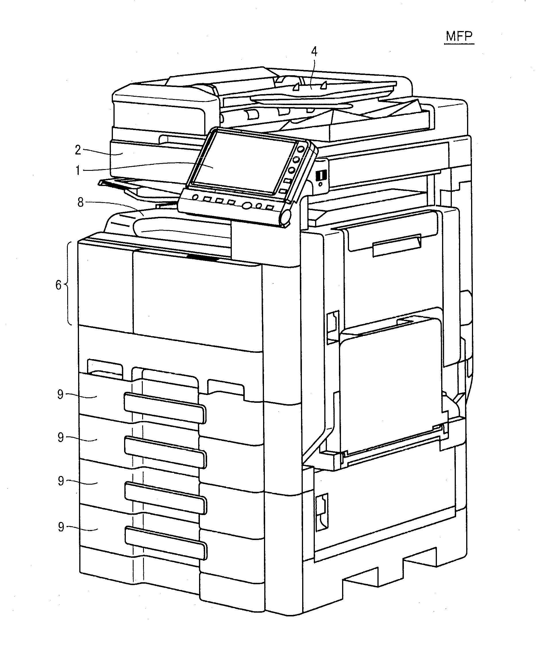
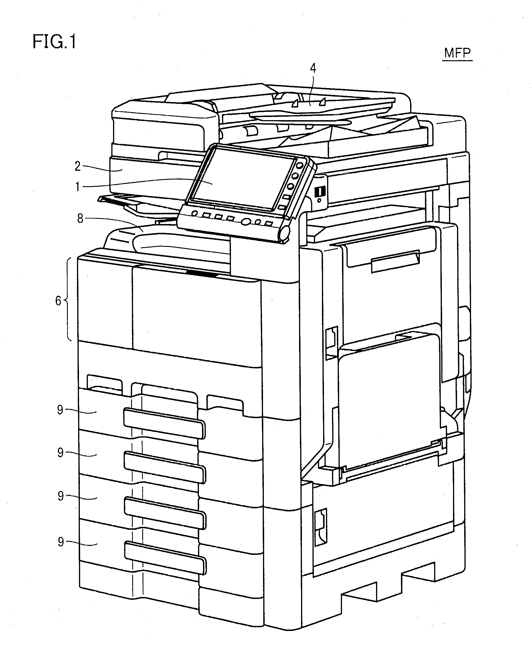
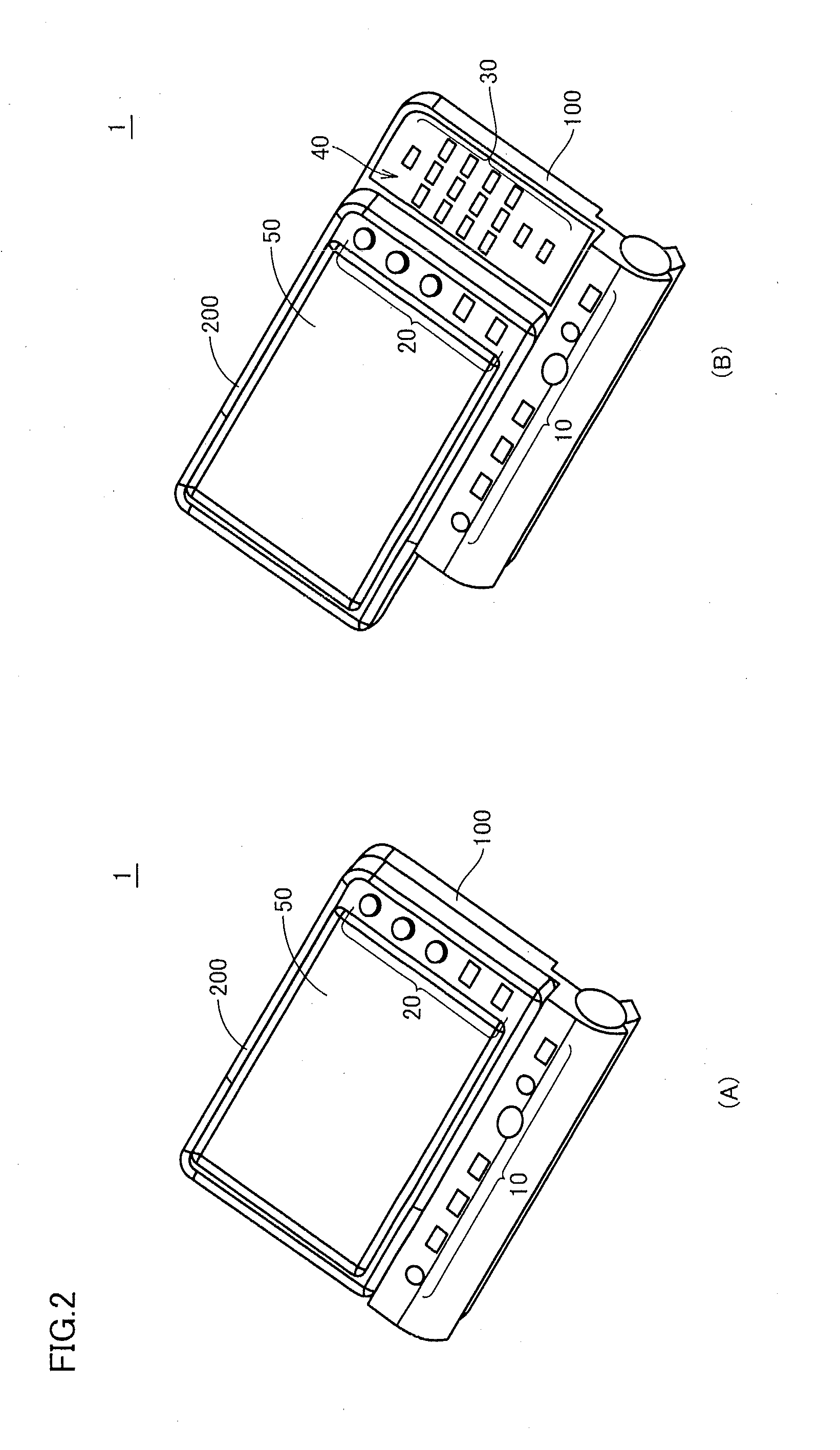
[0062]FIG. 1 is a perspective view illustrating an entire configuration of an image forming apparatus on which an operation panel device according to an embodiment of the present invention is mounted. FIG. 1 illustrates a Multi-Function Peripheral (MFP) to which a plurality of functions such as a scanner function, a copy function, a facsimile function, a netw...


PUM


Abstract

An operation panel device with a display surface is provided with mounted on an image forming apparatus. The operation panel device includes first and second panels that are relatively movable along a plane parallel to the display surface. The first panel is fixed to the image forming apparatus. The second panel is disposed opposite to the image forming apparatus with respect to the first panel. A projection area of the second panel to the plane parallel to the display surface is smaller than a projection area of the first panel. Each of the first and second panels includes a first group of keys disposed in a region that is exposed independent from relative positions of the first and second panels. The first panel includes a second group of keys disposed in a region that is exposed only when the first panel and second panels do not overlap each other.

Description

[0001]This application is based on Japanese Patent Application No. 2011-062590 filed with the Japan Patent Office on Mar. 22, 2011, the entire content of which is hereby incorporated by reference.BACKGROUND OF THE INVENTION[0002]1. Field of the Invention[0003]The preset invention relates to an operation panel device and an image forming apparatus provided therewith.[0004]2. Description of the Related Art[0005]Various operation keys such as a mode switching key and a one-touch key are provided in an operation panel device used to operate a conventional image forming apparatus. Recently, the number of such operation keys disposed in the operation panel device is increased with the increasing number of functions of the image forming apparatus, and the operation panel device tends to become larger in size. Disposition of the operation keys also tend to become complicated on an operation surface of the operation panel device.[0006]In an image forming apparatus that has a function of disc...

Claims


Application Information

Patent Timeline
IPC IPC(8): G06F3/12
CPCG06F1/1624H04N1/00384H04N1/00408G03G15/5016H04N1/00501H04N1/00533H04N2201/0094H04N1/00474
Inventor UCHIDA, SATOMI
Owner KONICA MINOLTA BUSINESS TECH INC
Why Eureka
Try Eureka