
Solar panels grounding clip

a solar panel and grounding clip technology, applied in the direction of solar heat collector safety, connection contact member material, coupling device connection, etc., can solve the problems of increasing the overall system price, adding material and labor costs, and the grounding lugs themselves are expensive and time-consuming to install, so as to reduce the number of distinct grounding connections and cost-effective

Active Publication Date: 2012-09-27
SOLAR MOUNTING SOLUTIONS
View PDF5 Cites 78 Cited by
  • Summary
  • Abstract
  • Description
  • Claims
  • Application Information

AI Technical Summary

Benefits of technology

[0017]It is another object of the present invention to provide a grounding clip which reduces the number of distinct grounding connections required in a solar panel system.
[0018]It is a further object of the present invention to provide a cost effective grounding solution for solar panels in terms of initial material, installation and maintenance costs.

Problems solved by technology

The grounding lugs themselves are expensive and time consuming to install and the wiring adds both material and labor cost which increase the price of the overall system.
However, none of the prior art systems are designed to capable of addressing all of these concerns.
Although the washers of the '129 patent appear superior as compared to conventional grounding practices using grounding lugs, they are limited in their ability to reduce the number of grounding clips required to ground a racking system and the solar panels mounted on the racking system.

Method used


Image

  • Solar panels grounding clip
  • Solar panels grounding clip
  • Solar panels grounding clip

Examples


Embodiment Construction

[0102]As used herein, the terms “grounding” or “ground” shall be construed to mean electrically grounding (“ground”) an object or bonding the object to a ground potential. As used herein, the term “bonding” means permanently joining to form an electrically conductive path that ensures electrical continuity and that the formed bond has the capacity to safely conduct any current likely to be imposed. The term “about” is used herein to mean approximately, roughly, around, or in the region of. When the term “about” is used in conjunction with a numerical range, it modifies that range by extending the boundaries above and below the numerical values set forth. In general, the term “about” is used herein to modify a numerical value above and below the stated value by a variance of 20 percent up or down (higher or lower).

[0103]The present invention is configured to electrically bond more than two objects with only one grounding clip and aids in meeting bonding and grounding requirements of ...


PUM


Abstract

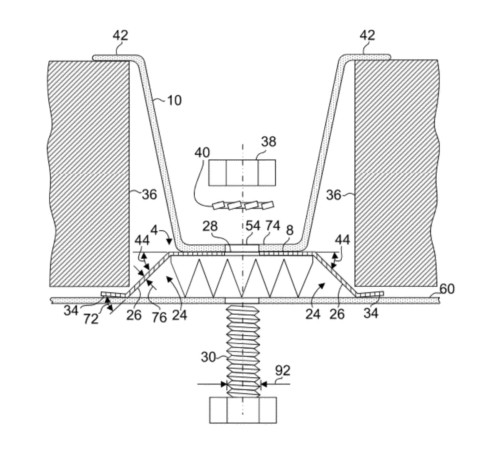
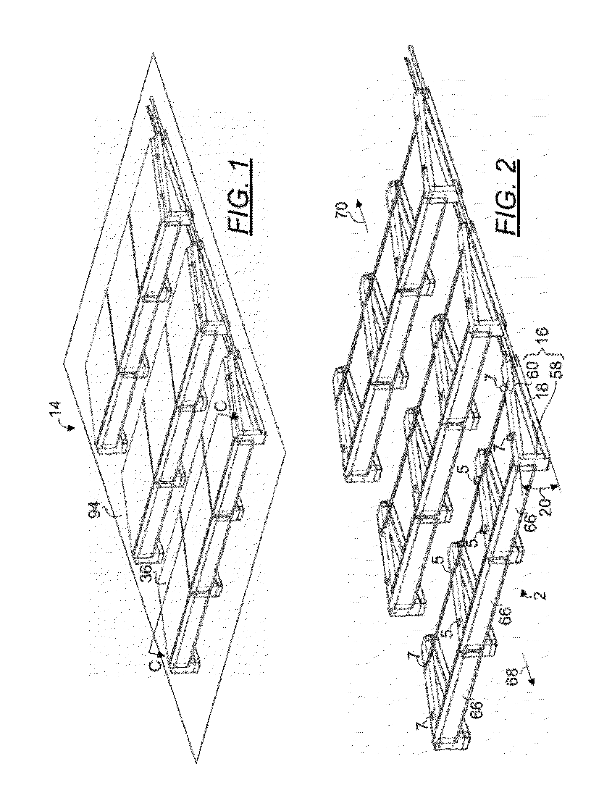
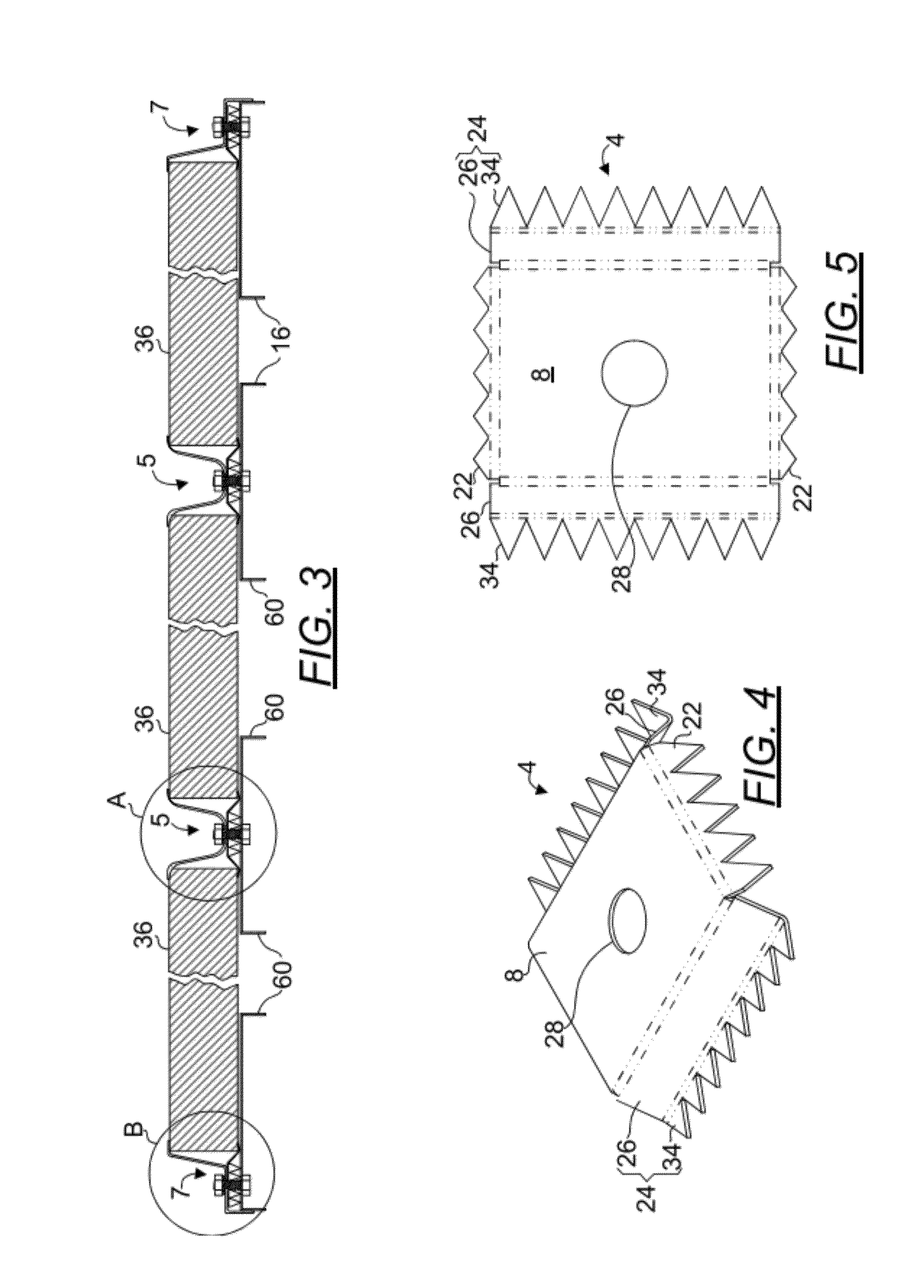
A grounding clip for electrically bonding at least three objects in one action. In use, the grounding clip is interposed between at least three objects such that the first and second banks of teeth are configured to penetrate the objects to electrically bond them. The grounding clip has a planar body, a pair of opposingly disposed first banks of teeth that extend downwardly and outwardly from the planar body at an angle. There is also a pair of opposingly disposed second banks of teeth formed of a rotatable plate disposed in a plane at an angle and extending downwardly and outwardly from the planar body. The second banks of teeth terminate in a plurality of second teeth disposed upwardly and in an angled plane with respect to the rotatable plate.

Description

RELATED APPLICATIONS AND PRIORITY CLAIM[0001]This application claims priority to provisional application U.S. Ser. No. 61 / 467,245 filed Mar. 24, 2011. Said application is incorporated by reference herein in its entirety.BACKGROUND OF THE INVENTION[0002]1. The Field of the Invention[0003]The present invention is directed generally to grounding clips, and in particular, to grounding clips for solar panels.[0004]2. Background Art[0005]Recent advancements in solar cell technology and skyrocketing fossil fuel prices have prompted many businesses to consider solar energy as an alternative energy source. Many commercial buildings have flat roofs. These large expanses of flat spaces present ideal opportunities to place solar panels as they are typically not publically accessible and free from significant natural debris such as leaves or shade cast by trees or buildings.[0006]As labor costs are high, it is imperative to resort to a solar racking system having a grounding system that is simpl...

Claims


Application Information

Patent Timeline
Patent Type & Authority Applications(United States)
IPC IPC(8): H01R13/648
CPCF24J2/4638F24J2/5233F24J2/5239H02S20/24Y02E10/47Y02B10/20Y02B10/12F24J2/5258F24S40/85F24S2025/6008F24S25/16F24S25/13F24S25/636Y02E10/50Y02B10/10
Inventor RIVERA, ANGEL M.MAYER, STANLEY E.
Owner SOLAR MOUNTING SOLUTIONS
Learn More