Anchoring device for a line in a skull bore hole

Inactive Publication Date: 2012-09-27
CARAG AG
View PDF13 Cites 25 Cited by
  • Summary
  • Abstract
  • Description
  • Claims
  • Application Information

AI Technical Summary

Benefits of technology

[0008]The device according to the invention not only fixes the line, but it also prevents said line from being squeezed or kinking Since the lines cannot be bent too strongly and hence squeezing or kinking is made impossible, the functionality thereof is ensured. This is i

Problems solved by technology

US 2005/0182464 discloses further anchoring dev

Method used


Image

  • Anchoring device for a line in a skull bore hole
  • Anchoring device for a line in a skull bore hole
  • Anchoring device for a line in a skull bore hole

Examples


first embodiment

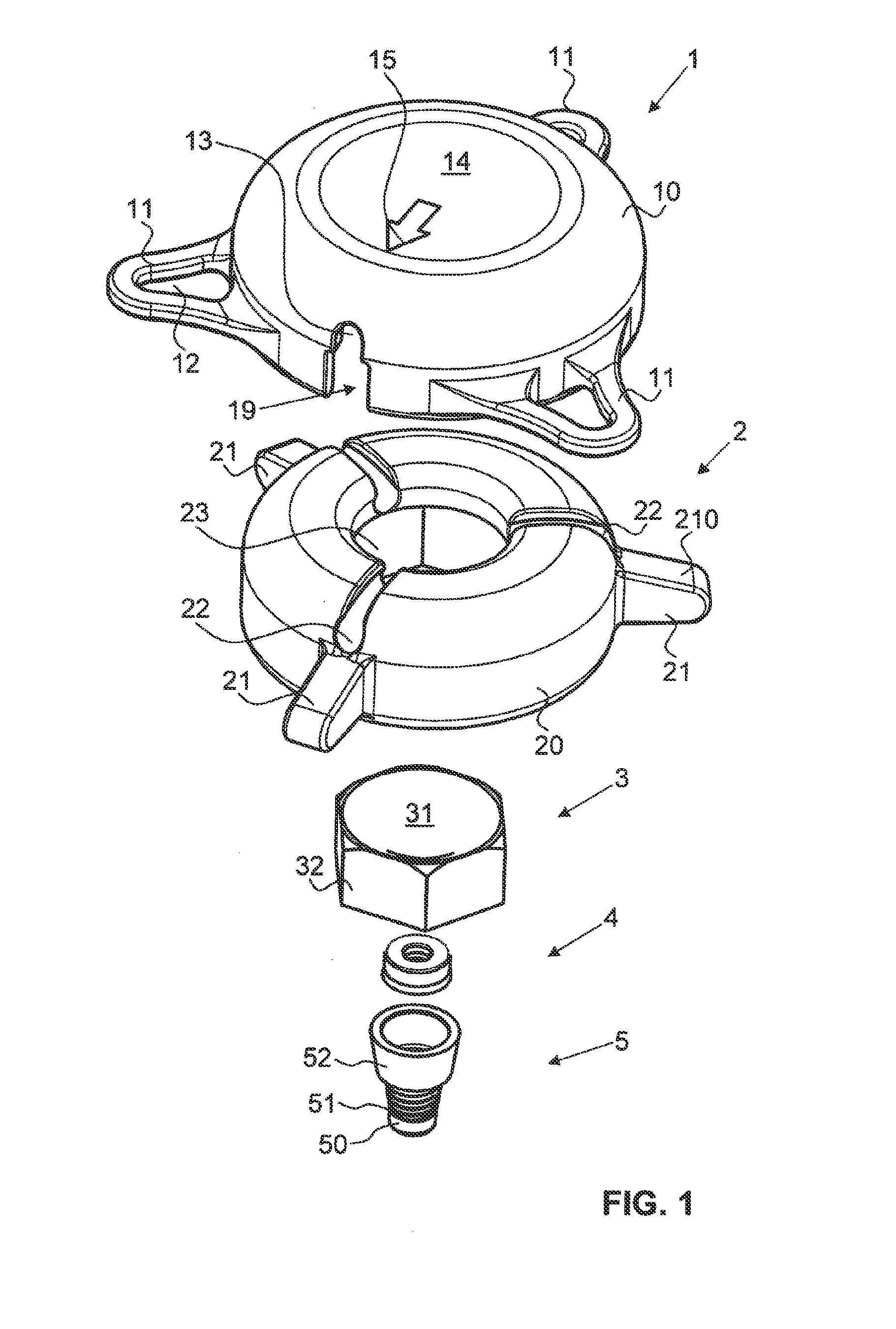
[0023]FIG. 1 shows an exploded view of an anchoring device according to the invention in a perspective view as per a first embodiment;

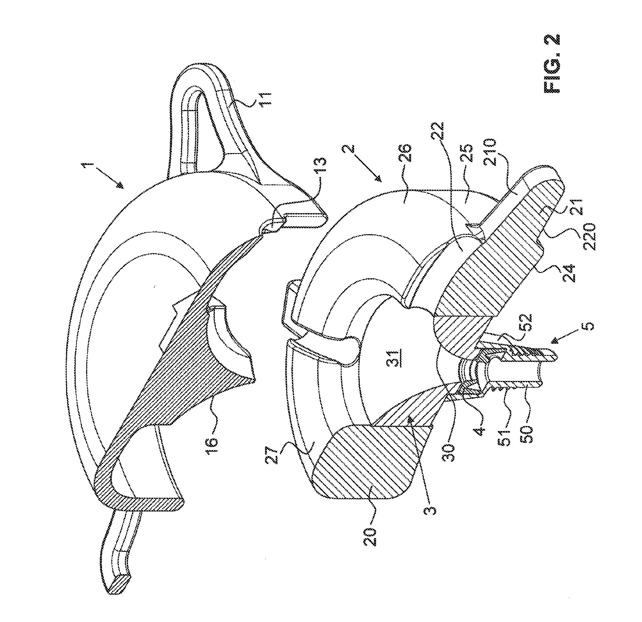
[0024]FIG. 2 shows a partial exploded view of the anchoring device as per FIG. 1 in a partial section;

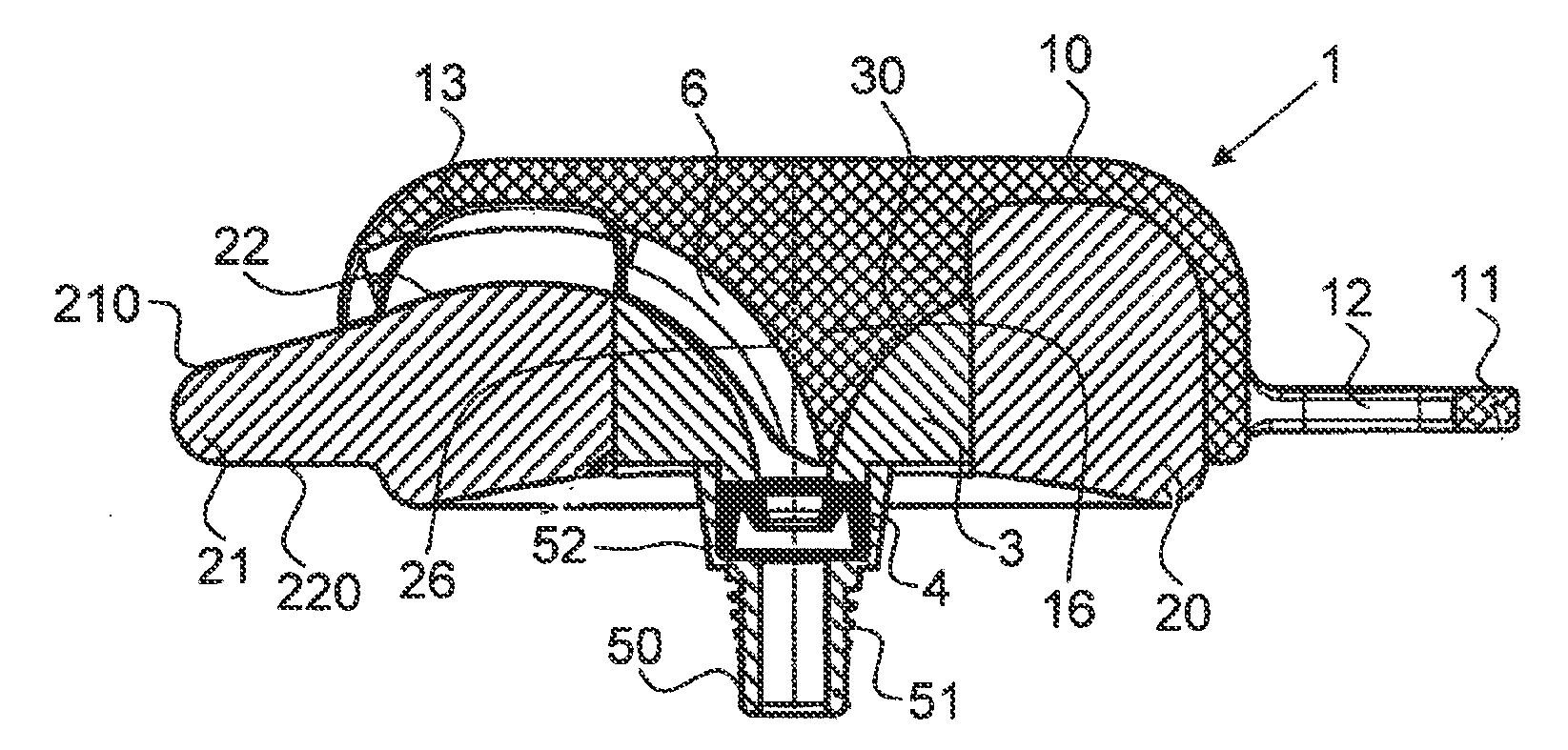
[0025]FIG. 3 shows a longitudinal section through the anchoring device as per FIG. 1 in the assembled state;

[0026]FIG. 4 shows a view of a cover of the anchoring device as per FIG. 1 obliquely from below;

[0027]FIG. 5 shows a view of the anchoring device as per FIG. 3, assembled as intended, from a first side;

[0028]FIG. 6 shows a view of the anchoring device as per FIG. 5, from a second side;

second embodiment

[0029]FIG. 7 shows a perspective view of a base part according to the invention in a second embodiment;

[0030]FIG. 8 shows a perspective view of the base part as per FIG. 7 with a cover according to the invention as per this second embodiment, from a first side;

[0031]FIG. 9 shows a perspective view of the anchoring device as per FIG. 8, from a second side;

[0032]FIG. 10 shows a perspective view of the cover as per FIG. 9, from below;

[0033]FIG. 11 shows a partial section in an exploded view of the anchoring device according to the invention as per FIG. 8, from a first side; and

[0034]FIG. 12 shows a partial section of the anchoring device as per FIG. 11, from a second side.


PUM


Abstract

An anchoring device for anchoring a line in a skull bore hole comprises a base part and a cover that tightly closes the base part. The base part has a fastening element for fastening the base part in the bore hole and a passage opening for feeding the line from the bore hole to an outside of the anchoring device. A contact surface extending between the bore hole and the outside for laying the line is present in the base part. The contact surface is curved in a constant direction so that the line is guided from the skull interior to the outside in a constant direction and at a radius of curvature that is greater than or equal to a predefined minimum radius of curvature. Said anchoring device allows a line to be lead out of a bore hole of a skull at a flat angle without the line being bent too greatly or even kinked.

Description

CROSS REFERENCE TO RELATED APPLICATIONS[0001]The present application is a U.S. National Phase Application pursuant to 35 U.S.C. §371 of International Application No. PCT / CH / 2010 / 000306 filed Dec. 2, 2010, which claims priority to Swiss Patent Application No. 1907 / 09 filed on Dec. 11, 2009. The entire disclosure contents of these applications are herewith incorporated by reference into the present application.TECHNICAL FIELD[0002]The present invention relates to an anchoring device for anchoring a line in a skull bore hole.PRIOR ART[0003]The prior art has disclosed various methods and means for cerebral diagnostics and / or therapy, which require a line through a bore hole of a skull. Examples of these are devices for the electrical brain stimulation, for measuring the perfusion or the blood flow, for pressure measurements, for supplying medicaments and for the aspiration of tissue liquid.[0004]Here, the line is fixed or anchored in the bore hole in order to avoid inadvertent injury to...

Claims


Application Information

Patent Timeline
IPC IPC(8): A61M25/04
CPCA61M25/02A61M2025/0213A61N1/0539A61M2025/028A61M2025/0246
Inventor HUMMEN, JORGROTHLIN, CYRILLSTEINER, CLAUDIO
Owner CARAG AG
Why Eureka
Try Eureka