Serial port remote control circuit

a remote control circuit and serial port technology, applied in the field of control circuits, can solve problems such as inability to use serial ports for control

Inactive Publication Date: 2012-09-27
HONG FU JIN PRECISION IND (SHENZHEN) CO LTD +1
View PDF4 Cites 11 Cited by
  • Summary
  • Abstract
  • Description
  • Claims
  • Application Information

AI Technical Summary

Benefits of technology

[0015]In use, the connector J2 is connected to a serial port of the motherboard, the connector J3 is connected to a connector, which is set on the motherboard and connected to a memory of the motherboard, to transmit control programs stored in the memory to the microcontroller U1, the power connector J6 is connected to a power supply of the computer for receiving a 5V, and the connector J1 is electrically connected to a connector of a start device, for starting the microcontroller U1 by an external device when the microcontroller U1 can not be started from an inside memory of the microcontroller U1. The computer is powered on, the power circuit 50 provides the received 5V from the power connector J6 and the 3.3V converted from the 5V to the control circuit 10, the first interface circuit 20, the second interface circuit 30, and the output circuit 40. The microcontroller U1 receives control programs through the connector J3. The motherboard sends control instructions in the form of RS232 level signals to the level converting chip U2 through the connector J2. The level converting chip U2 converts the received RS232 level signals to TTL level signals and outputs the TTL level signals to the microcontroller U1. The microcontroller U1 converts the received TTL level signals to the physical bus signals and outputs the physical bus signals to the bus converting chip U3. The bus converting chip U3 converts the received physical bus signals to network bus signals and outputs the network bus signals to the remote devices through the network connectors J4 and J5, to control the remote devices to operate.

Problems solved by technology

However, in large-scale industrial machinery, using serial ports for control may not be feasible due to the distance between the controller and the serial port.

Method used


Image

  • Serial port remote control circuit
  • Serial port remote control circuit
  • Serial port remote control circuit

Examples


Embodiment Construction

[0007]The disclosure, including the accompanying drawings, is illustrated by way of example and not by way of limitation. It should be noted that references to “an” or “one” embodiment in this disclosure are not necessarily to the same embodiment, and such references mean at least one.

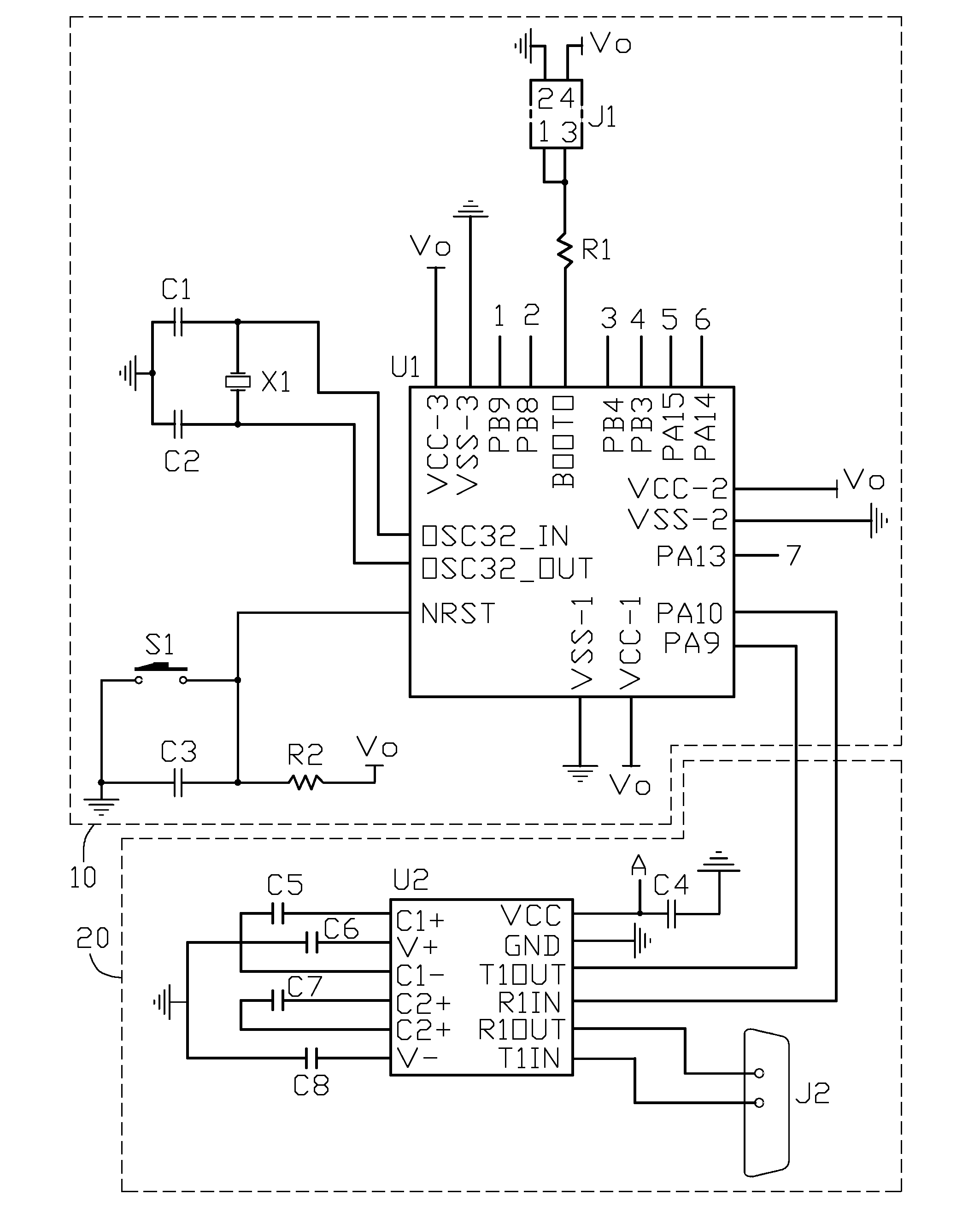
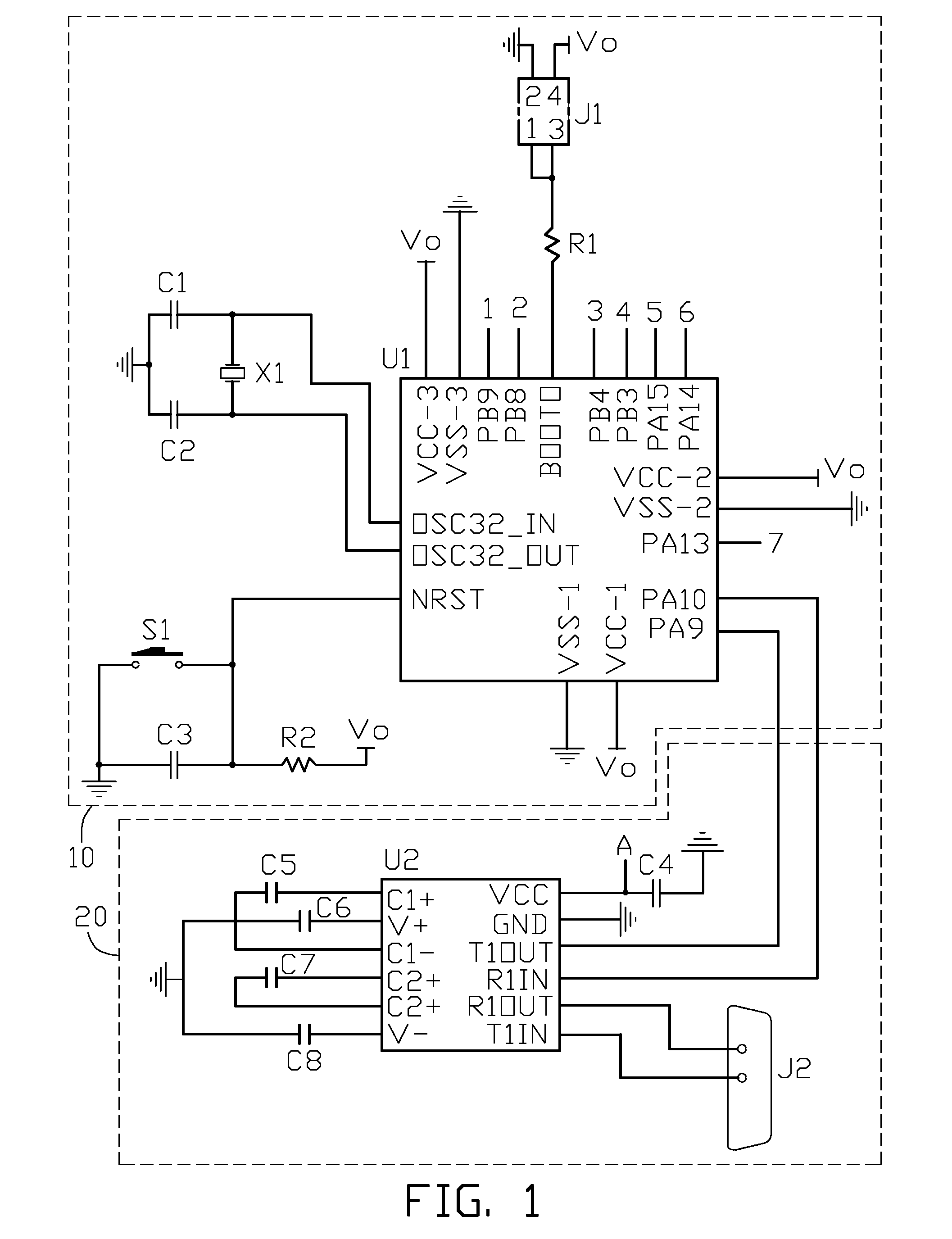
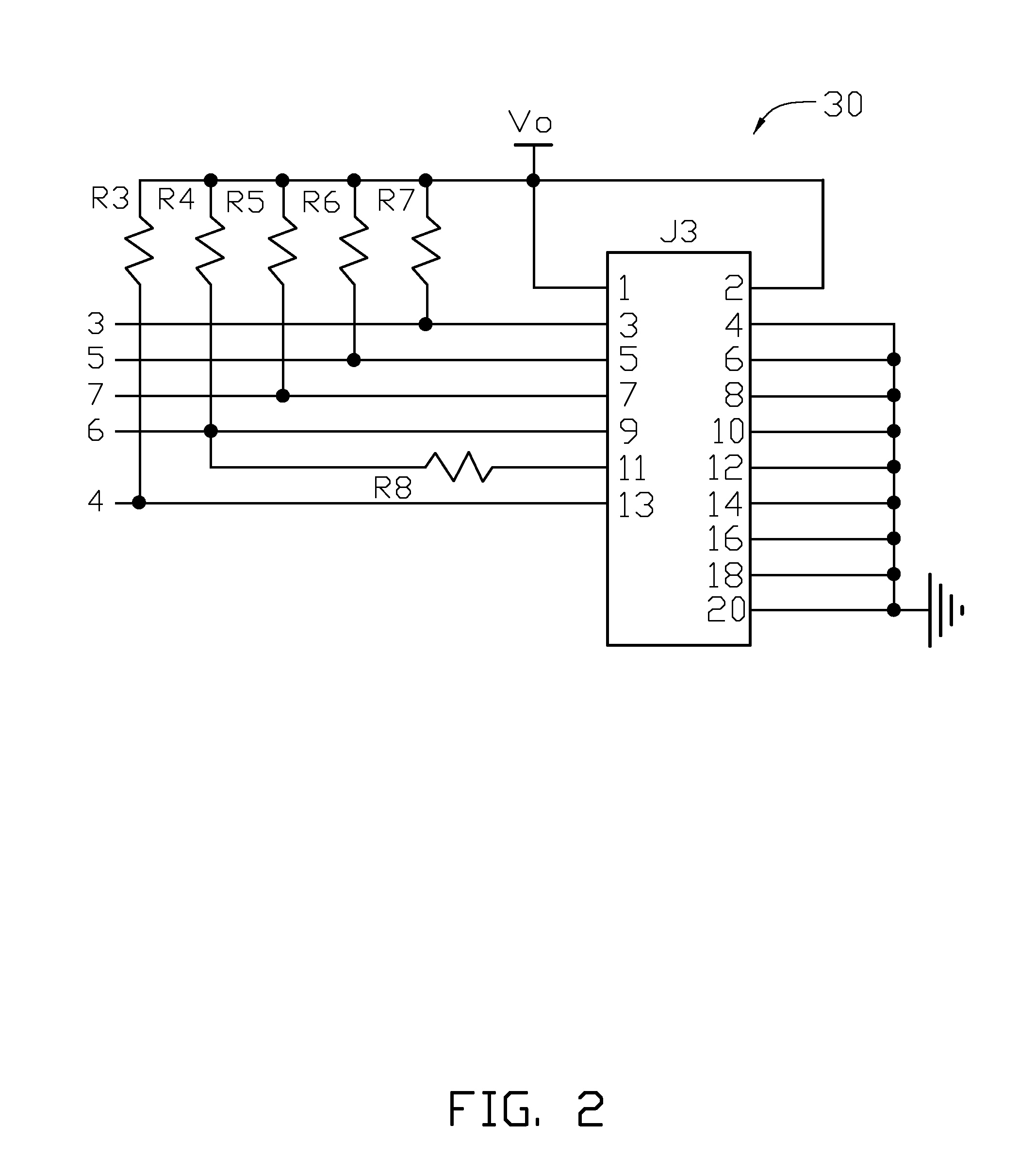
[0008]Referring to FIG. 1 to FIG. 4, an exemplary embodiment of a serial port remote control circuit includes a control circuit 10, a first interface circuit 20, a second interface circuit 30, an output circuit 40, and a power circuit 50.

[0009]The first interface circuit 20 is connected to a motherboard (not shown) of a computer and also to the control circuit 10. The first interface circuit 20 converts recommended standard 232 (RS232) level signals from the motherboard to transistor-transistor logic (TTL) level signals and output the TTL level signals to the control circuit 10. The control circuit 10 converts the received TTL level signals to physical bus signals and outputs the physical bus signals t...


PUM


Abstract

A serial port remote control circuit includes a first interface circuit, a control circuit, an output circuit, and a power circuit. The first interface circuit converts recommended standard 232 (RS232) level signals to transistor-transistor logic (TTL) level signals or vice versa. The control circuit is connected to the first interface circuit, to convert the TTL level signals to physical bus signal or vice versa. The output circuit is connected to the control circuit, to convert the received physical bus signals from the control circuit to network bus signals or vice versa. The power circuit outputs a first voltage and a second voltage converted from the first voltage to the control circuit, the first interface circuit, and the output circuit.

Description

BACKGROUND[0001]1. Technical Field[0002]The present disclosure relates to control circuits, and particularly relates to a control circuit controlled through a serial port.[0003]2. Description of Related Art[0004]For management and control of electronic devices / appliances, serial ports, such as recommended standard 232 (RS232) are widely used. A maximum data transfer rate of the RS232 is 20 kilobits per second (Kbps), and a maximum transmission distance of the RS232 is 15 meters. However, in large-scale industrial machinery, using serial ports for control may not be feasible due to the distance between the controller and the serial port. Therefore, there is room for improvement in the art.BRIEF DESCRIPTION OF THE DRAWINGS[0005]Many aspects of the present embodiments can be better understood with reference to the following drawings. The components in the drawings are not necessarily drawn to scale, the emphasis instead being placed upon clearly illustrating the principles of the prese...

Claims


Application Information

Patent Timeline
Patent Type & Authority Applications(United States)
IPC IPC(8): G06F13/14
CPCG05B19/0423G06F13/385G05B2219/25171
Inventor GUO, QIANGTAN, MIN
Owner HONG FU JIN PRECISION IND (SHENZHEN) CO LTD
Why Eureka
Try Eureka