Bootstrap driving circuit

A bootstrap drive circuit and circuit technology, which is applied in the direction of logic circuit connection/interface layout, logic circuit coupling/interface using field effect transistors, etc., can solve problems such as the inability to directly connect single-chip MCUs and TTL devices, and the high price of integrated modules

Inactive Publication Date: 2012-10-24
HUIZHOU SANHUA IND
View PDF6 Cites 11 Cited by
  • Summary
  • Abstract
  • Description
  • Claims
  • Application Information

AI Technical Summary

Problems solved by technology

[0002] In the field of bootstrap drive circuits, integrated modules are generally used to complete the bootstrap function in the industry, but int...

Method used


Image

  • Bootstrap driving circuit

Examples


Embodiment

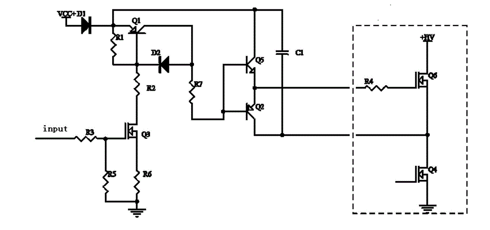
[0013] Such as figure 1 As shown, the bootstrap drive circuit of the present invention is provided with an input interface input, including a low-voltage control high-voltage MOS tube circuit, a switch signal circuit, a totem pole output circuit and a MOS tube Q6 arranged at the output end. The low-voltage control high-voltage MOS tube circuit includes a MOS tube Q3, and a current limiting resistor R6 connected in series with the source of the MOS tube Q3; the gate of the MOS tube Q3 is also provided with bias resistors R3 and R5, and the gate is connected to the input through the bias resistor R3. The interface input is connected and grounded through the bias resistor R5. The switching signal circuit includes a transistor Q1 and a diode D2 connected between the collector and the base of the transistor Q1; the base of the transistor Q1 is connected to the drain of the MOS transistor Q3 via a resistor R2. The collector of the triode Q1 is used as the output end of the switch s...


PUM


Abstract

The invention provides a bootstrap driving circuit. The bootstrap driving circuit comprises a totem pole output circuit, and further comprises a low-pressure-controlled high-pressure MOS (metal oxide semiconductor) pipe circuit and a switching signal circuit which are connected, wherein the low-pressure-controlled high pressure MOS pipe circuit is arranged on the input end of the bootstrap driving circuit, and the switching signal circuit is connected with the totem pole output circuit. The bootstrap driving circuit provided by the invention fully utilizes the conventional discrete element to reduce the circuit cost, input-output interfaces of the circuit are relatively easy to be connected with a MCU (microprogrammed control unit) of a singlechip, a TTL (transistor-transistor logic) device, and the cost is low.

Description

technical field [0001] The invention relates to the field of power switch driving or signal driving, in particular to a bootstrap driving circuit. Background technique [0002] In the field of bootstrap drive circuits, integrated modules are generally used in the industry to complete the bootstrap function, but integrated modules (such as IR21 series) are expensive and have defects such as inability to directly interface with single-chip MCUs and TTL devices. Contents of the invention [0003] The purpose of the invention is to overcome the defects and deficiencies of the prior art, provide a bootstrap drive circuit, make full use of existing discrete components to reduce circuit costs, make the input and output interfaces of the circuit more easily connected with single-chip MCU, TTL devices, and reduce the cost. low. [0004] The object of the present invention is achieved through the following technical solutions: the bootstrap drive circuit includes a totem pole outpu...

Claims


Application Information

Patent Timeline
IPC IPC(8): H03K19/0185
Inventor 甘勇刚张世桐咸立坤
Owner HUIZHOU SANHUA IND
Why Eureka
Try Eureka