Image Display Apparatus and Computer Apparatus Employing Same

Inactive Publication Date: 2012-10-04
VAREL INT IND +1
View PDF11 Cites 10 Cited by
  • Summary
  • Abstract
  • Description
  • Claims
  • Application Information

AI Technical Summary

Benefits of technology

[0009]Thus, an object of the present invention is to provide a thin-screen image display

Problems solved by technology

Thus, recognition of the displayed contents i

Method used


Image

  • Image Display Apparatus and Computer Apparatus Employing Same
  • Image Display Apparatus and Computer Apparatus Employing Same
  • Image Display Apparatus and Computer Apparatus Employing Same

Examples


first embodiment

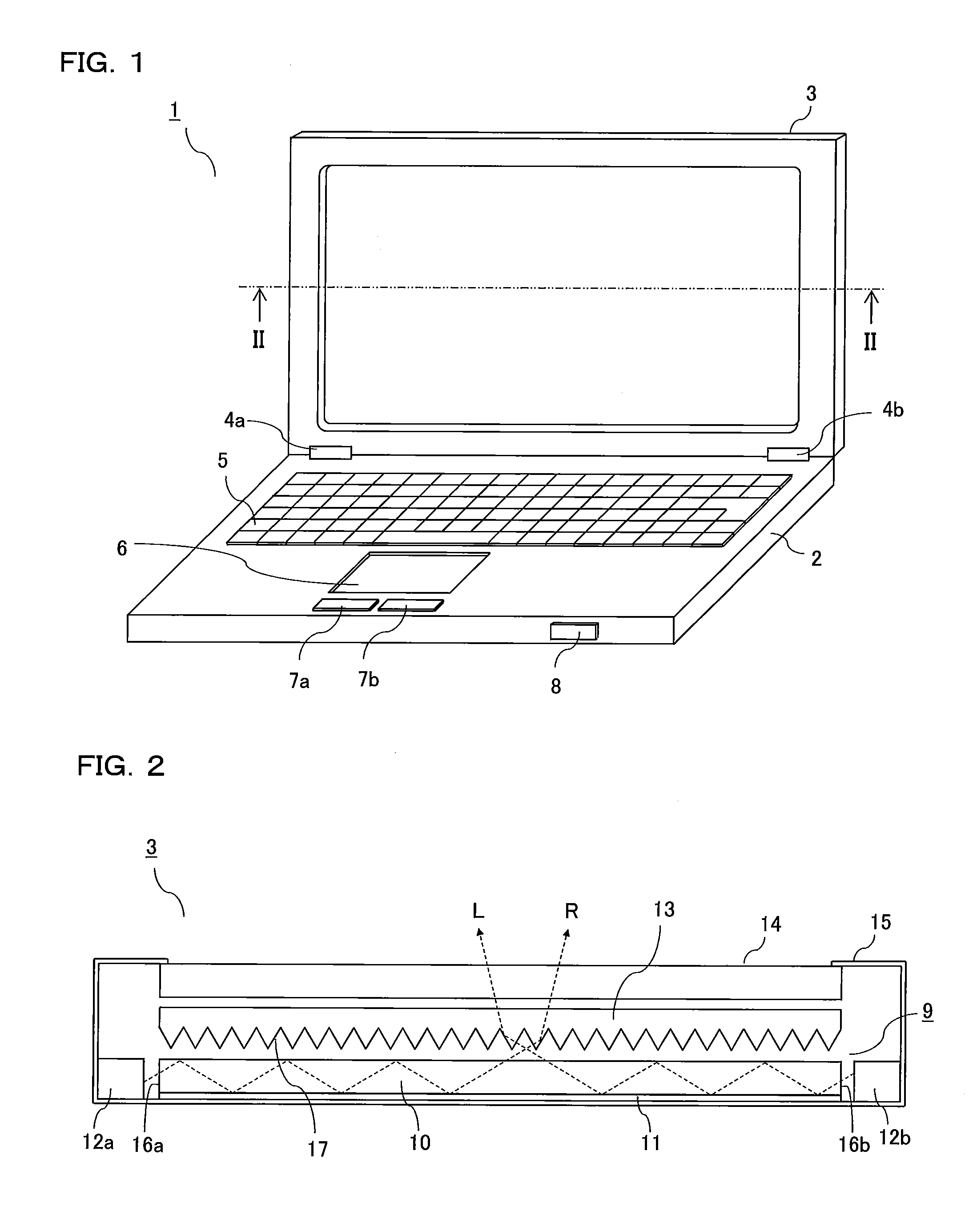
[0018]FIG. 1 is a perspective view showing a notebook-type personal computer employing an image display apparatus according to a first embodiment.

[0019]A personal computer 1 has: a main body 2 in which a CPU and a storage device are accommodated; and an image display apparatus 3. The image display apparatus 3 is attached to the main body 2 through hinges 4a and 4b in a manner that opening and closing are allowed freely. The main body 2 has a plurality of keys 5, a touchpad 6, buttons 7a and 7b, and a power switch 8. The main body 2 further has: a plurality of connection terminals such as USB terminals; LED lamps; switches; and the like. Illustration of these items is omitted.

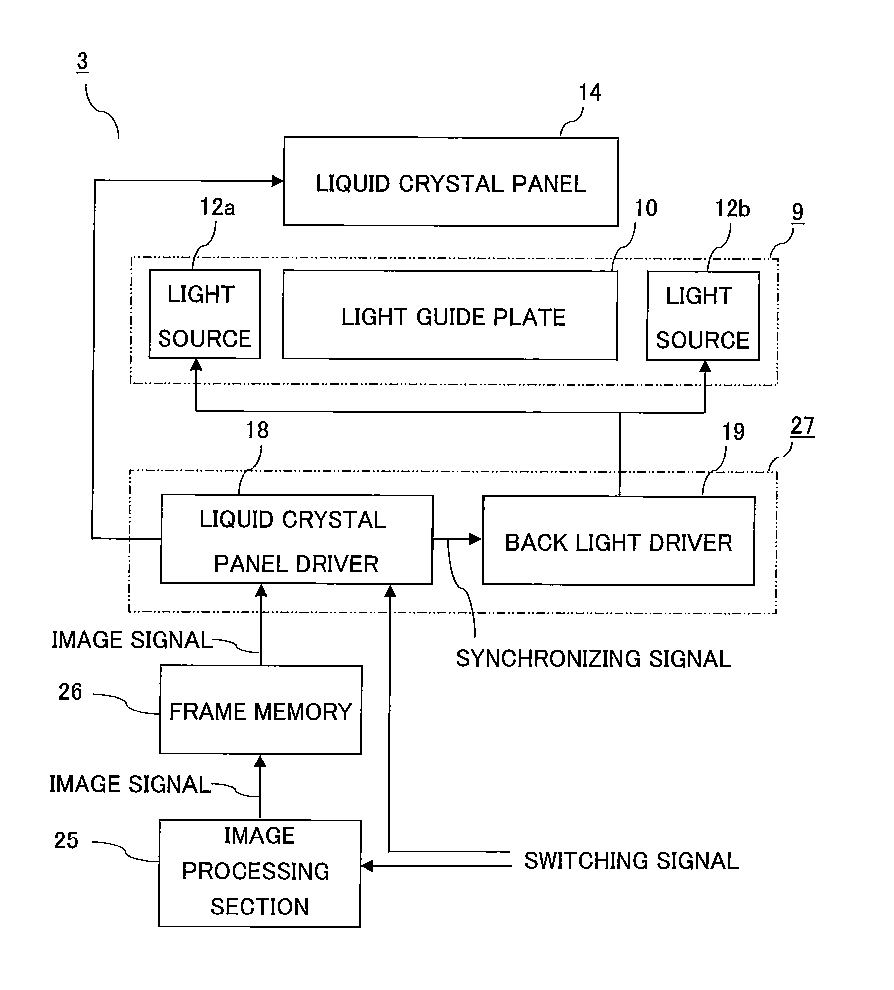
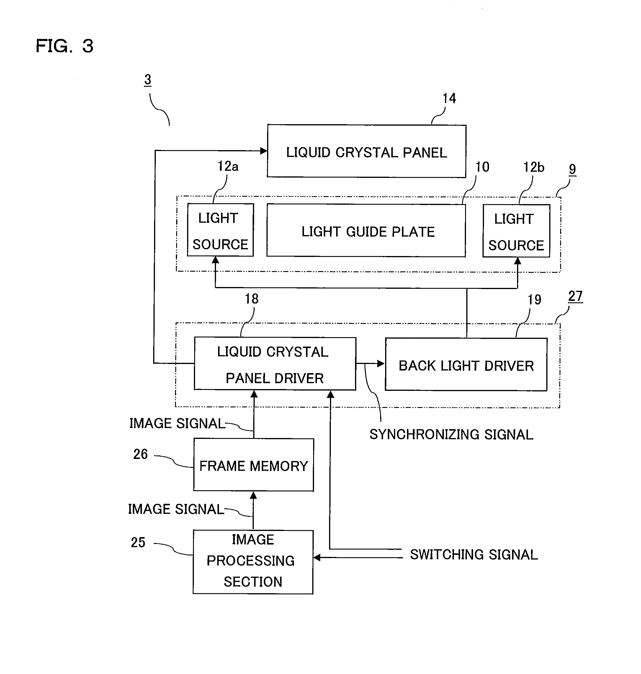
[0020]FIG. 2 is a schematic configuration diagram showing an image display apparatus according to the first embodiment, which is a sectional view taken along line II-II in FIG. 1.

[0021]The image display apparatus 3 has: a liquid crystal panel 14; a back light device 9 arranged on the rear side of the liquid crys...

second embodiment

[0041]FIG. 5 is a sectional view of an image display apparatus according to a second embodiment, which corresponds to FIG. 2.

[0042]The image display apparatus 3 shown in FIG. 5 is remarkably different from the first embodiment in that the back light device 9 is constructed using a pair of light guide plates 20a and 20b each having a rectangular flat plate shape. The light guide plates 20a and 20b are arranged in this order on the rear side of the prism sheet 13.

[0043]The one light source 12a is arranged along the side-surface 21 of the light guide plate 20a and emits light into the light guide plate 20a through the side-surface 21. The light emitted from the light source 12a undergoes total reflection repeatedly in the inside of the light guide plate 20a so as to be converted into surface-emitted light. A part of the light having entered the light guide plate 20a exits from the rear face of the light guide plate 20a, then passes through the light guide plate 20b, then is reflected b...


PUM


Abstract

An image display apparatus comprises: a liquid crystal panel; and a back light device on the rear face of the liquid crystal panel. The back light device includes: a light guide plate; a reflective sheet; a first and second light sources; and a prism sheet, and emits, to the right relative to the direction of viewing the liquid crystal panel, light emitted from the first light source and emits, to the left relative to the direction of viewing the liquid crystal panel, light emitted from the second light source. On the liquid crystal panel, a partial image obtained by omitting a part of an entire image and a partial image complementary to this are displayed alternately. The light sources and are controlled such as to be turned on alternately in synchronization with the displaying of the partial images on the liquid crystal panel.

Description

CROSS REFERENCE TO RELATED APPLICATION[0001]This application claims priority to Japanese Patent Application No. 2011-079812, filed on Mar. 31, 2011, the entire contents of which are incorporated herein by reference.BACKGROUND OF THE INVENTION[0002]1. Field of the Invention[0003]The present invention relates to an image display apparatus employed in a notebook-type personal computer or the like.[0004]2. Description of the Background Art[0005]In recent years, electronic devices such as notebook-type personal computers, portable phones, and smart phones employing liquid crystal displays are widely used. This causes increasing demands for security protection and privacy protection. Thus, techniques for preventing peeping by persons other than the user have been proposed.[0006]Japanese Laid-Open Patent Publication No. 2005-6881 discloses a technique for, in a game machine provided with an image display apparatus, preventing neighboring game players from peeping into displayed contents on...

Claims


Application Information

Patent Timeline
IPC IPC(8): G09G3/36
CPCG09G3/003G02B6/0068G02B6/0076G09G2358/00
Inventor HATAKEYAMA, ATSUSHI
Owner VAREL INT IND
Why Eureka
Try Eureka