
Liquid discharge apparatus

Active Publication Date: 2012-10-04
BROTHER KOGYO KK
View PDF4 Cites 2 Cited by
  • Summary
  • Abstract
  • Description
  • Claims
  • Application Information

AI Technical Summary

Benefits of technology

[0008]An object of the present teaching is to provide a liquid discharge apparatus in which the discharge performance of a recording head can be maintained by generating the flow of a liquid in a communication channel by utilizing the flushing operation in which the amount of consumption of the liquid is smaller than that consumed in the purge operation.
[0014]In this way, the flow is generated in the liquid contained in the communication channel by effectively utilizing the flushing operation in which the amount of consumption of the liquid is small so that the liquid contained in the communication channel is moved as much as possible and thus it is possible to prevent any bubble or the like from staying in the communication channel. Therefore, the discharge performance can be maintained without increasing the amount of consumption of the liquid.

Problems solved by technology

Therefore, even when only the flushing operation is performed, it is impossible to suppress the increase in viscosity of the ink in the communication channel and the staying of the bubble in the communication channel.
As a result, it is impossible to mitigate the harmful effects of the water hammer phenomenon, and the discharge performance of the recording head is lowered.
When the degree of the increase in viscosity of the ink in the communication channel is high, it is impossible in some cases to discharge the ink from the interior of the communication channel even when the purge operation is performed.
However, the amount of ink consumption in the purge operation is larger than that in the flushing operation.
Therefore, if the frequency of execution of the purge operation is raised, the ink is uselessly consumed.

Method used


Image

  • Liquid discharge apparatus
  • Liquid discharge apparatus
  • Liquid discharge apparatus

Examples


Embodiment Construction

[0023]An embodiment of the present teaching will be explained below with reference to the drawings.

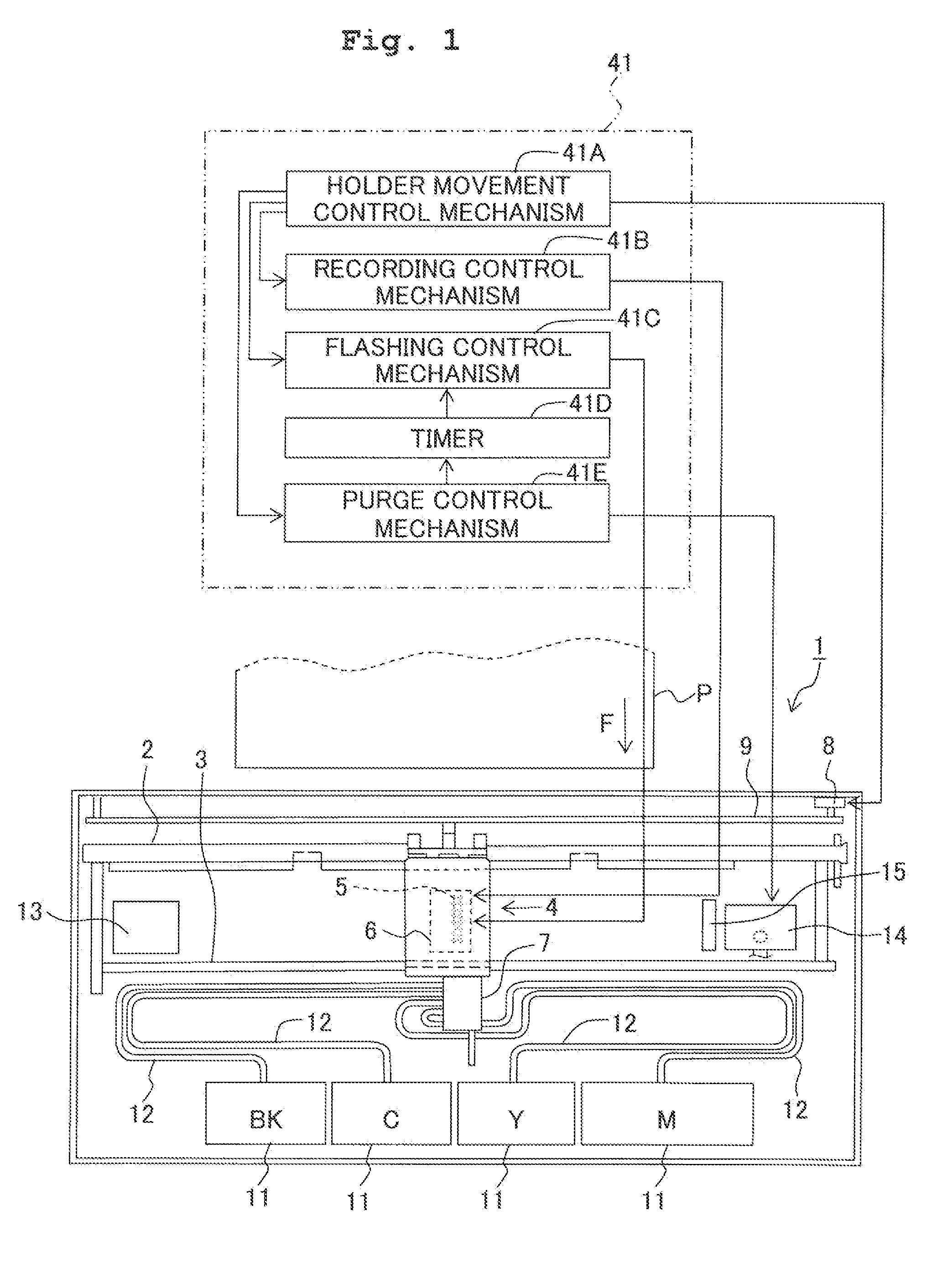
[0024]In the following explanation, it is assumed that the side of, for example, the ink-jet type recording apparatus and the recording head, on which the ink is discharged, is designated as “lower surface” and “downward direction”, and the side, which is opposite thereto, is designated as “upper surface” and “upward direction”. With reference to FIG. 1, it is assumed that the left end side of the drawing is designated as “leftward direction”, the right end side is designated as “rightward direction”, the lower edge side of the drawing is designated as “frontward”, and the upper edge side of the drawing is designated as “backward”.

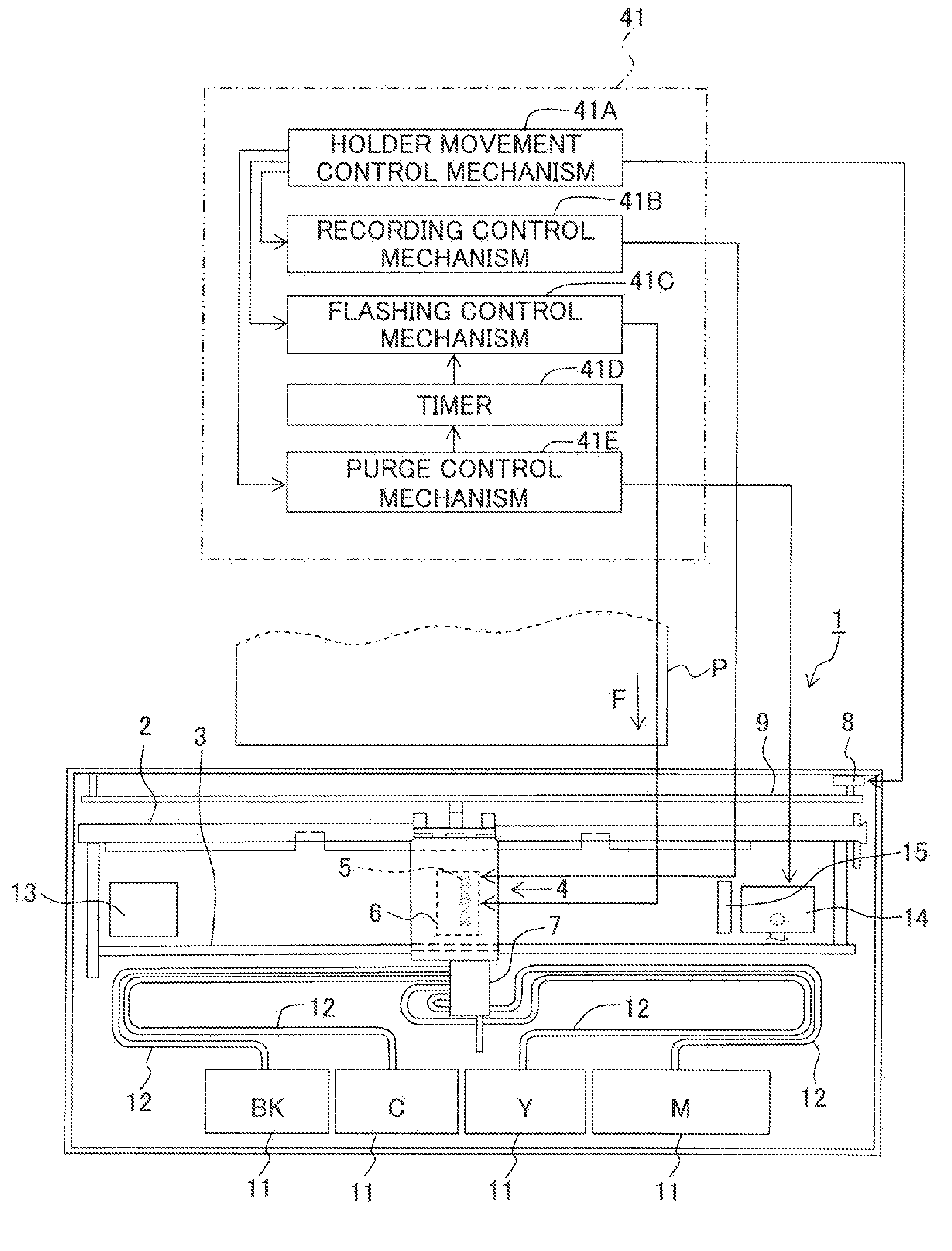
[0025]As shown in FIG. 1, two guide shafts 2, 3 are provided in parallel in an ink-jet type recording apparatus 1. A head holder 4, which functions as a carriage, is slidably supported by the guide shafts 2, 3. A recording head 6 (liquid discharge head) havin...


PUM


Abstract

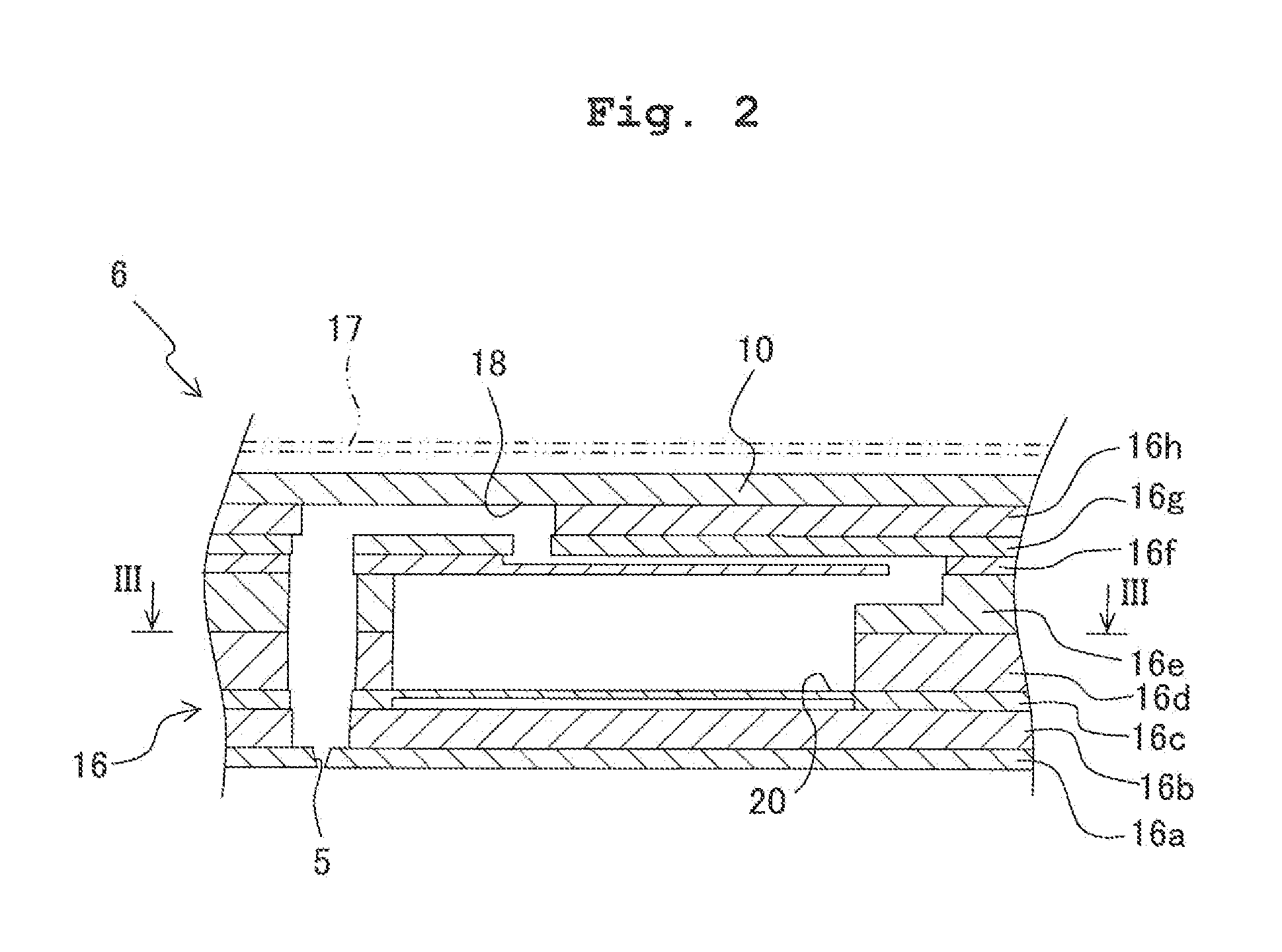
There is provided a liquid discharge apparatus including a liquid discharge head having a plurality of nozzles; a common chamber; a liquid chamber; a liquid supply port; and a communication channel; and a discharge control mechanism which controls the liquid discharge head to perform a discharge operation of discharging the liquid from the nozzles to the medium. The discharge control mechanism controls the liquid discharge head to perform a flushing operation, as the discharge operation, so that the liquid is discharged from a first nozzle group in a discharge mode, which is different from a discharge mode of a second nozzle group, to generate a flow of the liquid in the communication channel.

Description

CROSS REFERENCE TO RELATED APPLICATION[0001]The present application claims priority from Japanese Patent Application No. 2011-072898, filed on Mar. 29, 2011, the disclosure of which is incorporated herein by reference in its entirety.BACKGROUND OF THE INVENTION[0002]1. Field of the Invention[0003]The present invention relates to a liquid discharge apparatus which discharges a liquid.[0004]2. Description of the Related Art[0005]An ink jet type recording apparatus is known as an example of the liquid discharge apparatus which discharges a liquid (ink), including a recording head which has a discharge surface formed with a plurality of nozzles for discharging the ink, a recording control mechanism which controls the recording operation for performing the recording by driving the recording head and discharging the ink from the nozzles to the recording medium, and a flushing control mechanism which allows the ink to be discharged from the nozzles by driving the recording head distinctly ...

Claims


Application Information

Patent Timeline
IPC IPC(8): B41J29/38
CPCB41J2/16526
Inventor TAKATA, MASAYUKISHINDO, TATSUYA
Owner BROTHER KOGYO KK
Learn More