

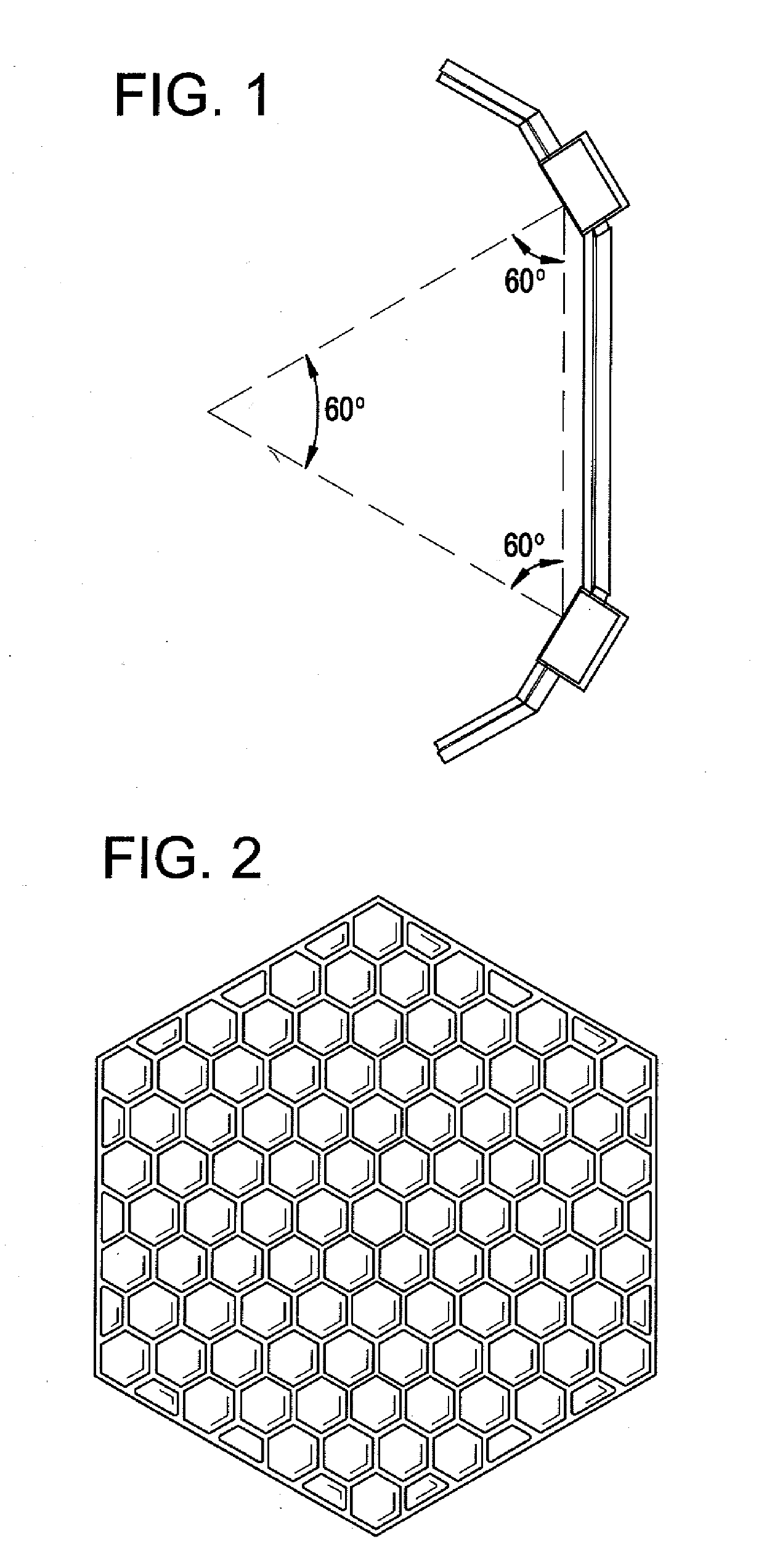
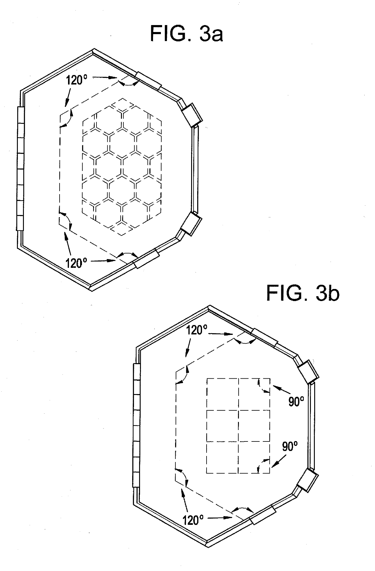
Hexagonal 2-dimensional reflection phase grating diffuser
- Summary
- Abstract
- Description
- Claims
- Application Information
AI Technical Summary
Benefits of technology
Problems solved by technology
Method used
Image

Examples
Embodiment Construction
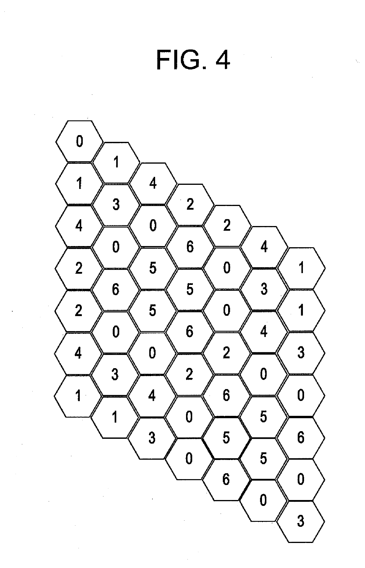
[0029]The preset invention relates to a new reflection phase grating diffuser consisting of divided hexagonal wells whose depth is based on a chosen number theoretic design. The number of hexagonal elements in a given design will depend on a chosen prime number. For example, utilizing a quadratic residue number theory sequence with prime number 7, the base unit will contain 49 divided hexagonal cells, designed using the Chinese Remainder Theorem as shown in FIG. 4.
[0030]Since 2D diffusers scatter in multiple planes, a receiver in the bright zone will experience a scattered energy that is attenuated more than for a 1D diffuser (provided multiple grating lobes are present). The number of grating lobes is squared if a 1D of width Nw and 2D diffuser of size Nw×Nw are compared, where N is a prime and w is the width of one of the elements in the unit cell. Therefore, the energy in each lobe will reduce by 10 log10(m), where m is the number of grating lobes present for the 1D diffuser.
[003...
PUM
 Abstract
Description
Claims
Application Information