Retro-illumination and eye front surface feature registration for corneal topography and ocular wavefront system

Inactive Publication Date: 2012-10-04
INNOVATIVE VISUAL SYST
View PDF3 Cites 19 Cited by
  • Summary
  • Abstract
  • Description
  • Claims
  • Application Information

AI Technical Summary

Benefits of technology

[0009]In FIG. 4 we show the front view of the eye with the retro-illuminated light source turned off. In this eye the iris patterns show up well. In other eyes, some veins can be seen in the sclera. It is also possible to place artificial marks on the sclera to identify a specific meridian. By considering the automatically calculated limbus contour and outer most ring, we can define a region where “good” registration features can be automatically selected from the iris image. The definition of “good” registration features are those that have nearly perpendicular image gradients. An example of this would be a “corner like” feature in an image. In addition to these automatically detected features, the user can interactively select points of interest from the sclera such as blood vessel forks or artificially placed marks. The set of automatic and interactively selected points can

Problems solved by technology

In some cases the corneal aberrations or the ocular aberrations may not be accurately determined, for example, due to image processing errors.
In th

Method used


Image

  • Retro-illumination and eye front surface feature registration for corneal topography and ocular wavefront system
  • Retro-illumination and eye front surface feature registration for corneal topography and ocular wavefront system
  • Retro-illumination and eye front surface feature registration for corneal topography and ocular wavefront system

Examples


Embodiment Construction

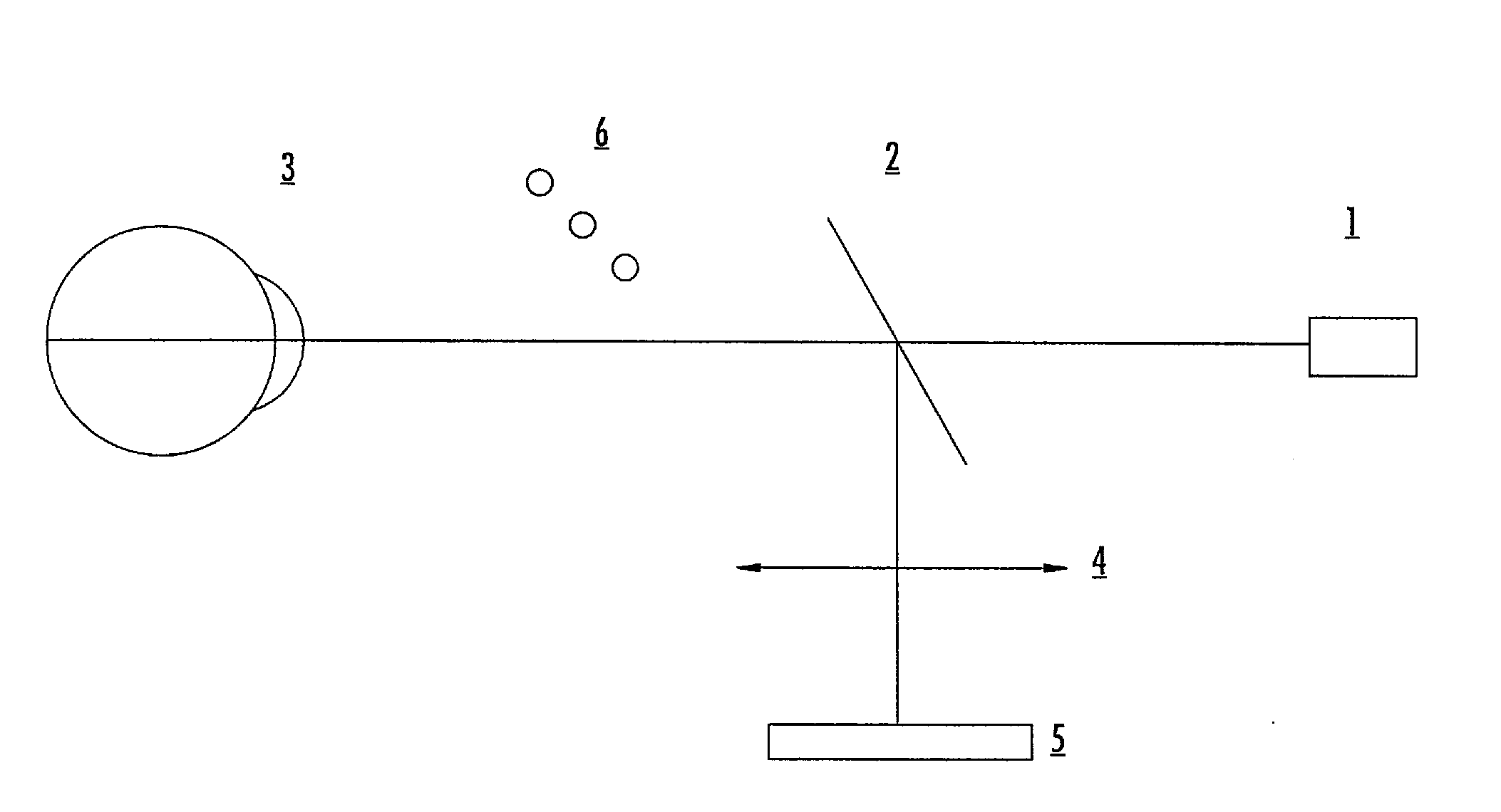
[0022]The basic optical layout for the retro-illumination and the front eye image features acquisition is shown in FIG. 6. Here, a near IR beam of light originates at SLD 1 and is directed though beam splitter 2 toward the eye 3. This beam forms a diffuse reflection at the retina and the light is directed out of the eye filling the entrance pupil and back illuminating the toric IOL within the eye. Light from the back lit toric IOL is directed by beam splitter 2 toward the lens 4 and forms an image on the camera sensor 5. This is the retro-illuminated image of the toric IOL. Immediately after the retro-illuminated image is captured, the SLD 1 is turned off, and the near IR LEDs 6 forming the light for the corneal topography rings are turned on. This light reflects off the front of the eye including the iris and sclera and is directed by beam splitter 2 to lens 4 and also forms an image on camera sensor 5. This second image is thus captured within a camera frame duration (typically 33...


PUM


Abstract

A method of obtaining a retro-illumination image using the beacon from an ocular wavefront path and the camera for the corneal topography path of the combined system. A digital image of the retro-illuminated view of the IOL, iris pattern and sclera is obtained. An interactive display of the retro-illuminated image is presented to the user to allow them to identify the orientation marks on the IOL. These marks identify the orientation of the IOL and an overlay line can be used to display this orientation. In addition, a 360 degree overlay can be used to enhance the display of this orientation line.

Description

RELATED APPLICATIONS[0001]This application claims the benefit of priority under 35 U.S.C. 119(e) of U.S. Provisional Patent Application No. 61 / 467,229, filed Mar. 24, 2011, entitled, “RETROILLUMINATION AND EYE FRONT SURFACE FEATURE REGISTRATION FOR CORNEAL TOPOGRAPHY AND OCULAR WAVEFRONT SYSTEM”, the entirety of which is incorporated herein by reference.FIELD OF THE INVENTION[0002]The present invention relates to systems and methods for human vision correction, and in particular, to a method of retro-illumination and eye front surface feature registration.BACKGROUND OF THE INVENTION[0003]Corneal topography systems provide a detailed surface description of the front of the eye's corneal surface in a mathematical form. Ocular wavefront systems provide a detailed description of the optical state for the entire eye. Together these optometric and ophthalmic systems provide information of the eye's optical errors and how to correct them using a wide range of methods including spectacles, ...

Claims


Application Information

Patent Timeline
IPC IPC(8): A61B3/14
CPCA61F2/1637A61B3/10
Inventor SARVER, EDWIN J.SANDERS, DONALD R.
Owner INNOVATIVE VISUAL SYST
Why Eureka
Try Eureka