
Taillight antitheft system

Inactive Publication Date: 2012-10-04
NICHOLS TONY
View PDF6 Cites 7 Cited by
  • Summary
  • Abstract
  • Description
  • Claims
  • Application Information

AI Technical Summary

Benefits of technology

[0012]Embodiments of the present inventive concept provide a taillight antitheft system that remedies the problem of unauthorized LED removal, as set forth above, by simultaneously obstructing access to LEDs and permitting light emitted from the LEDs to at least partially pass therethough. As such, the present inventive concept prevents theft of the LEDs without materially interfering with the underlying purpose of the LEDs. Additionally, the present inventive concept is easily and economically manufactured and easily installed.
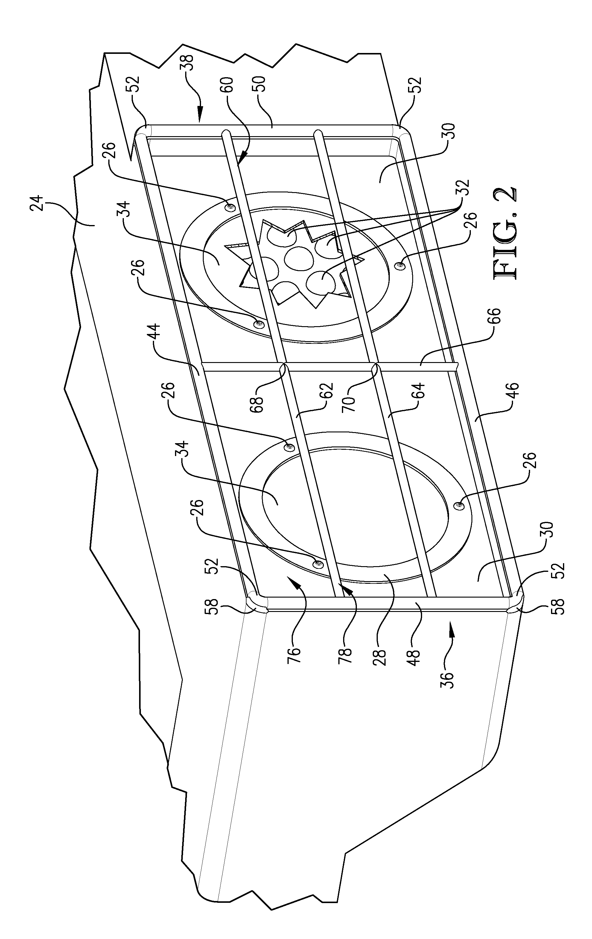
[0014]The aforementioned aspects may be achieved in one aspect of the present inventive concept by providing a taillight anti-theft system including a frame defining a planar void on an interior thereof, the frame having an abutment surface operable to engage a surface adjacent to a taillight, and an interior assembly fixedly attached to the frame and spanning the void. The interior assembly may be operable to (i) permit transmission of light from the taillight at least partially therethrough, and (ii) prevent removal of at least a portion of the taillight. The interior assembly may define an open area along the void operable to permit the transmission of the light.
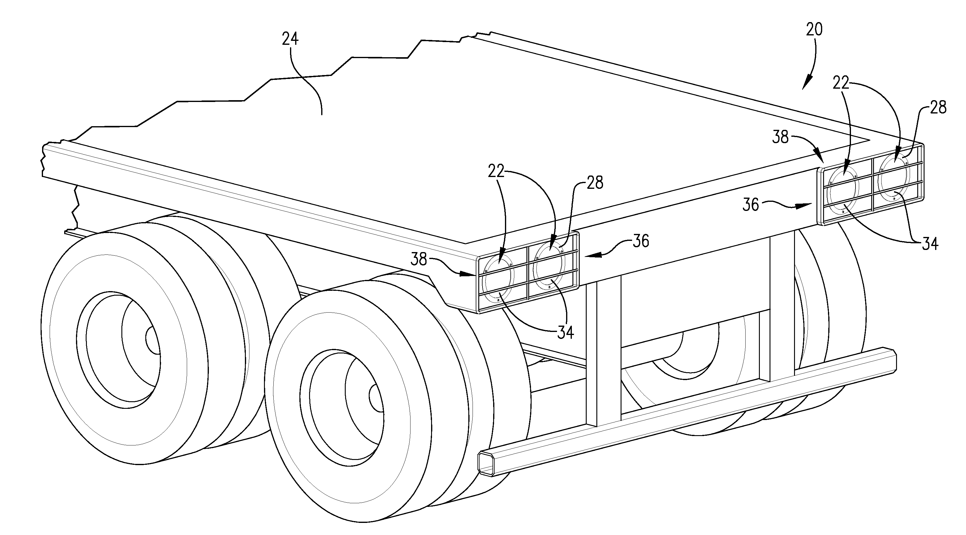
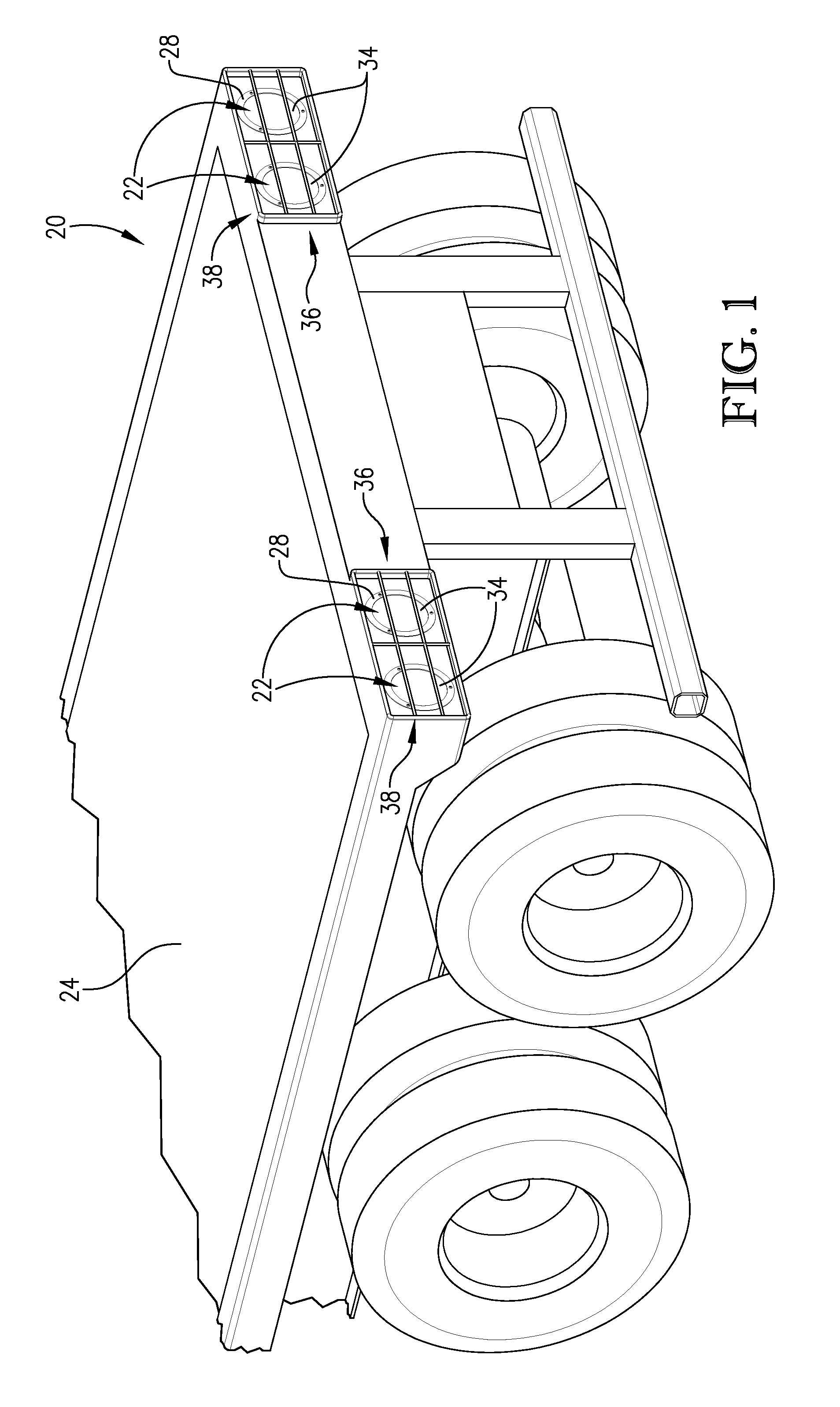
[0019]The aforementioned aspects may be achieved in another aspect of the present inventive concept by providing a trailer for transporting goods having taillights and taillight covers to prevent theft of the taillights. The trailer may include a plurality of taillight groupings on an end of a trailer, and a cover affixed to a surface adjacent to each of the groupings and operable to (i) permit transmission of light from each of the groupings at least partially therethrough, and (ii) prevent removal of at least a portion of each of the groupings. The cover may include a frame defining a planar void on an interior thereof, and an interior structure spanning the void. The interior structure may define an open area along the void operable to permit the transmission of the light, the open area comprising one of (i) at least 50% of the void, (ii) at least 75% of the void, and (iii) at least 80% of the void. The interior structure may be one of a bar network and / or a screen. The cover may be (i) permanently affixed to the surface adjacent to each of the groupings via a permanent-attachment process, and (ii) only removable from the surface via destroying a product of the permanent-attachment process. The product of the permanent-attachment process may be a weld.

Problems solved by technology

Until recently, a number of factors depressed the acceptance of LEDs as a replacement for traditional light sources.
A principal cause of the depressed acceptance rate of LEDs included their high cost of manufacturing, which translated to a high purchase price.
Thus, the use of LEDs in many applications was cost-prohibitive.
While the costs of manufacturing and purchasing LEDs have decreased and LEDs are being utilized in more applications, the purchase price is still high.
Consequently, applications where LEDs are exposed and easily removed render such LEDs subject to unauthorized removal or theft.
Additionally, given that semitrailers are often parked in desolate areas (e.g., large parking lots at truck stops or train yards), it is unlikely that an individual attempting to remove the LED taillights would be observed during the removal process and have its efforts thwarted.
In addition to the financial and time burdens required to replace LED taillights, theft of LED taillights is particularly problematic because an operator of the semitrailer may not immediately become aware of the theft and may continue to operate the semitrailer without LED taillights.
Operating a semitrailer on a highway or other roadway is extremely hazardous, especially during conditions of impaired visibility (e.g., during the night-time or fog).
Presently, there is no readily-available system to prevent or even deter theft of LED taillights of semitrailers.

Method used


Image

  • Taillight antitheft system
  • Taillight antitheft system
  • Taillight antitheft system

Examples


Embodiment Construction

[0029]The present inventive concept is susceptible of embodiment in many forms. While the drawings illustrate, and the specification describes, certain embodiments of the invention, it is to be understood that such disclosure is by way of example only. The principles of the present inventive concept are not limited to the particular disclosed embodiments.

[0030]With initial reference to FIGS. 1-3, a taillight antitheft system 20 is generally illustrated in an exemplary embodiment in use with taillight units 22 of a trailer 24 to prevent or at least deter theft of the taillight units 22 or a component thereof. Each of the taillight units 22 are mounted in groupings of two on either side of the trailer 24 via a plurality of screws 26 that secure a circumferential taillight unit frame 28 of each of the taillight units 22 to a trailer support surface 30. Each of the taillight units 22 house at least one and preferably a cluster of light-emitting diodes (LEDs) 32 (e.g., fifteen LEDs).

[003...


PUM

PropertyMeasurementUnit
Fractionaaaaaaaaaa
Lengthaaaaaaaaaa
Lengthaaaaaaaaaa

Abstract

A taillight antitheft system having a frame with an interior void having a bar network and / or a screen configured to be permanently mounted over a grouping of LED taillight units and to an adjacent-mounting surface via a welding process. In this manner, system obstructs access to the LED taillight units, thereby preventing unauthorized removal or theft thereof, while permitting light emitted from the LED taillight units to pass therethrough, thereby not materially interfering with the underlying purpose of the LED taillight units. The system is only removable from the mounting surface via destroying weld marks produced during the welding process.

Description

CROSS-REFERENCE TO RELATED APPLICATION[0001]This patent application claims priority to and is a continuation-in-part of U.S. patent application Ser. No. 13 / 074,411 filed Mar. 29, 2011, the entire contents of which is herein incorporated by reference in its entirety.BACKGROUND[0002]1. Field of the Invention[0003]The present inventive concept relates generally to an antitheft system for a light. More specifically, embodiments of the present inventive concept concern a light cover being particularly suitable for use as an antitheft system when the light cover is mounted to a taillight of a vehicle so as to prevent removal of the taillight or portions thereof.[0004]2. Description of the Related Art[0005]The advantages light emitting diodes (LEDs) relative to traditional light sources, (e.g., incandescent bulbs), are known. Principal advantages of LEDs over such traditional light sources include lower energy consumption, less occupied area, increased durability, and increased lifespan (e...

Claims


Application Information

Patent Timeline
IPC IPC(8): F21S8/10B23P11/00B60Q1/30
CPCF21V15/005Y10T29/49826B60Q1/305B60Q1/0005
Inventor NICHOLS, TONY
Owner NICHOLS TONY
Learn More