Method for Tracking Tumors in Bi-Plane Images

a tumor and image sequence technology, applied in the field of 3d objects tracking, can solve the problems of time-consuming, difficult to extend the above described methods to tracking tumors in sequences of images, and high method complexity

Active Publication Date: 2012-10-04
MITSUBISHI ELECTRIC RES LAB INC
View PDF0 Cites 18 Cited by
  • Summary
  • Abstract
  • Description
  • Claims
  • Application Information

AI Technical Summary

Benefits of technology

[0019]For inferring the 3D location, we use particle filtering, where each particle is a possible new location for the tumor. From the volume, each particle is mapped to the segmentation masks associated with the volume. By matching these segmentation hypothesis with the resulting

Problems solved by technology

Due to this property, graph cut methods tend to generate compact regions, even if the underlying appearance depicts elongated objects.
However, the modified process has to be repeated for different scales to determine the best match, which is time consuming.
However, that method is highly complex and r

Method used


Image

  • Method for Tracking Tumors in Bi-Plane Images
  • Method for Tracking Tumors in Bi-Plane Images
  • Method for Tracking Tumors in Bi-Plane Images

Examples


Embodiment Construction

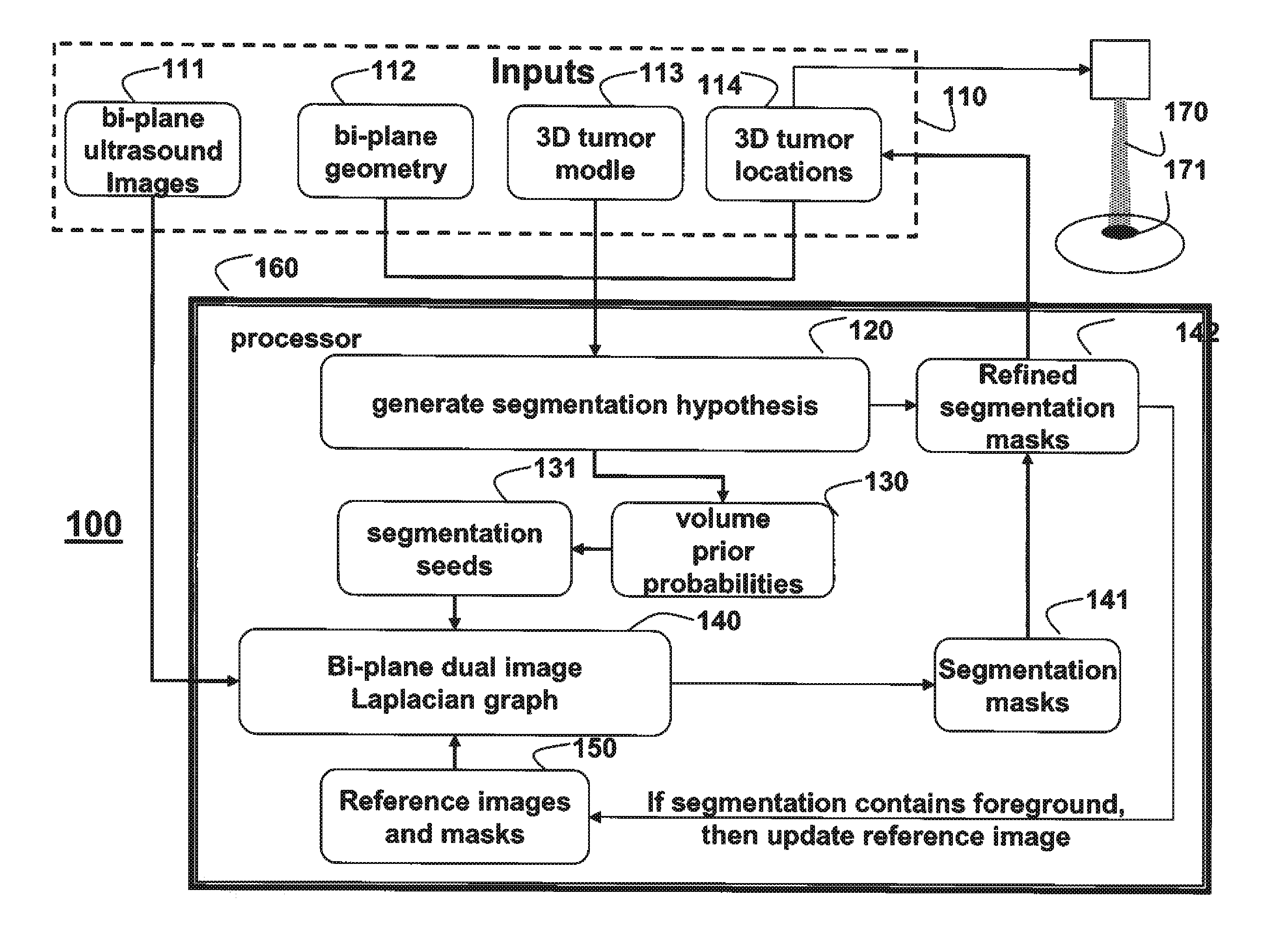
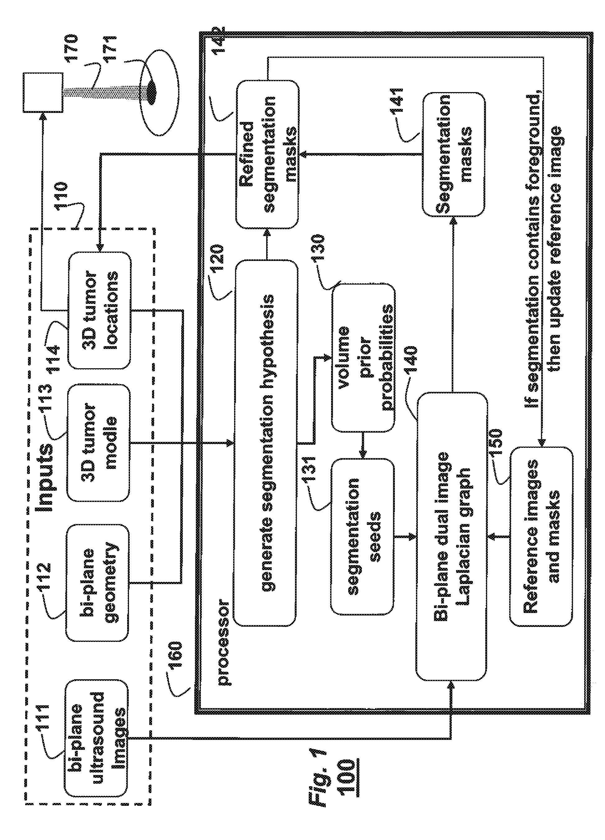
[0025]FIG. 1 shows a method 100 for tracking a 3D tumor in sequences of bi-plane images using a 3D model of the shape of the tumor as prior information according to embodiments of our invention.

[0026]Inputs 110 to the method include two sequences of pairs of bi-plane images 111, a bi-plane geometry 112, a 3D model 113 of the tumor, and an initial 3D tumor location 114. The initial location can be estimated or approximate. Iterations of the method update the location 114 as the tumor is tracked. In one embodiment, the bi-plane images are acquired by two ultrasound transducer arrays that are rotated with respect of each other to provide simultaneous views in two image planes. Hence, at each time instant, there is a pair of two images. It is understood that the invention can also be worked with other imaging modalities.

[0027]For each pair of current image in the sequence 111, a set of hypotheses are generated 120 using the 3D tumor model 113 given the bi-plane geometry 112, and the loc...


PUM


Abstract

A tumor is tracked in sequences of biplane images by generating a set of segmentation hypotheses using a 3D model of the tumor, a biplane geometry, and a previous location of the tumor as determined from the pairs of biplane images. Volume prior probabilities are constructed based on the set of hypotheses. Seed pixels are selected using the volume prior probabilities, and a bi-plane dual image graph is constructed using intensity gradients and the seed pixels to obtaining segmentation masks corresponding to tumor boundaries using the image intensities to determine a current location of the tumor.

Description

FIELD OF THE INVENTION[0001]This invention relates generally to tracking 3D objects, and more particularly to tracking a moving tumor in sequences of bi-plane images for the purpose of particle beam radiotherapy.BACKGROUND OF THE INVENTION[0002]Particle beam radiotherapy delivers charged particles to a tumor while minimizing damage to surrounding healthy tissue. An energy deposition profile of the particles has a Bragg peak. The peak occurs immediately before the particles come to rest. The profile can be controlled to deliver a maximum energy within a few millimeters of the range of the particles. Thus, the prescribed irradiation is focused on the tumor with little side scatter and broadening of the beam.[0003]However, due to random and systemic motion, the tumor must be tracked continuously in real-time during treatment. Several modalities such as ultrasound, X-ray, and magnetic resonance imaging (MRI), are used to track internal structures of the body. Among these, the ultrasound...

Claims


Application Information

Patent Timeline
IPC IPC(8): G06K9/34
CPCG06T7/0081G06T7/0087G06T7/0093G06T7/0097G06K9/6224G06T2207/20144G06T2207/20156G06T2207/30096G06T2207/10136G06T7/11G06T7/143G06T7/162G06T7/174G06T7/194G06V10/7635G06F18/2323
Inventor PORIKLI, FATIHHUSSEIN, MOHAMED
Owner MITSUBISHI ELECTRIC RES LAB INC
Why Eureka
Try Eureka