Optical packet switching system

a packet switching and optical technology, applied in the field of optical packet switching system, can solve problems such as degrading communication quality, and achieve the effect of reducing the optical packet discarding ra

Inactive Publication Date: 2012-10-04
FUJITSU LTD
View PDF5 Cites 16 Cited by
  • Summary
  • Abstract
  • Description
  • Claims
  • Application Information

AI Technical Summary

Benefits of technology

[0008]The present invention has been made in view of the foregoing circumstances, and a general purpose is to provide a technology for reducing the optical packet discarding rate in the optical packet switching method.

Problems solved by technology

However, as the usage rate of optical packet line increases as a result of increased number of optical packets to the network, the optical packet signals are frequently discarded, thereby possibly degrading the communication quality.

Method used


Image

  • Optical packet switching system
  • Optical packet switching system
  • Optical packet switching system

Examples


Embodiment Construction

[0049]The invention will now be described by reference to the preferred embodiments. This does not intend to limit the scope of the present invention, but to exemplify the invention.

[0050]Optical packet switching systems according to embodiments of the present invention will be described with reference to the drawings.

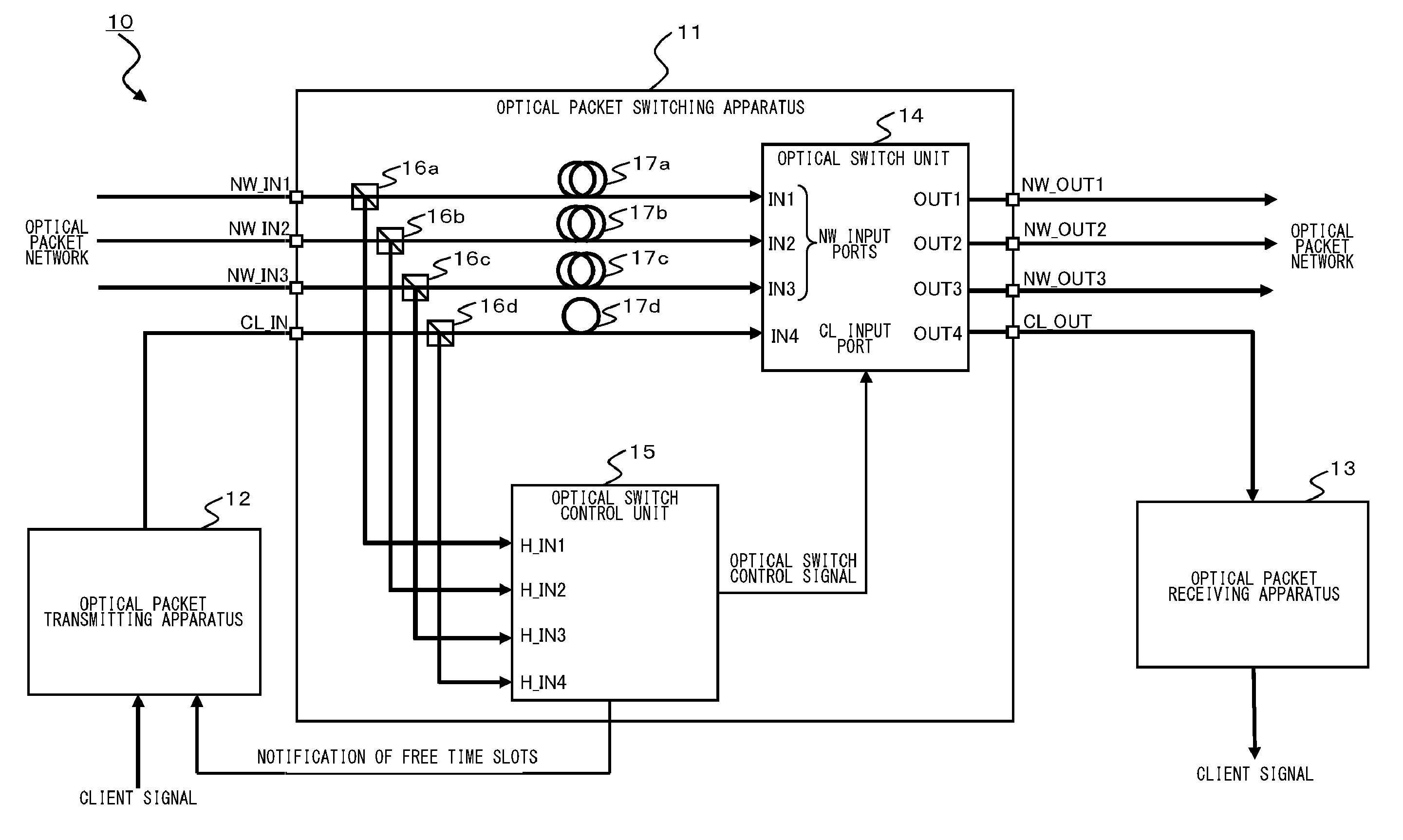
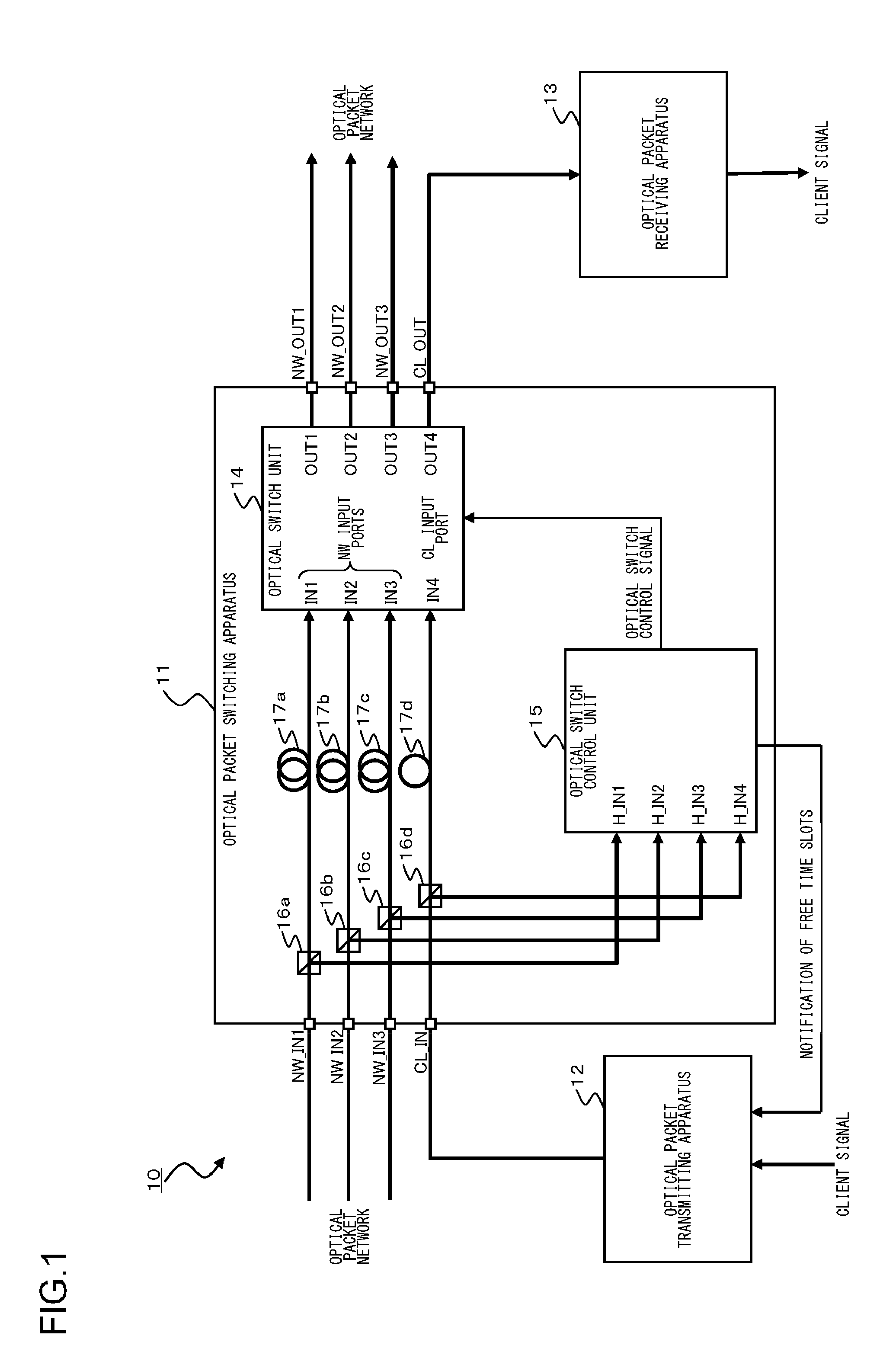
[0051]FIG. 1 shows an optical packet switching system 10 according to an embodiment of the present invention. As shown in FIG. 1, an optical packet switching system 10 includes an optical packet switching apparatus 11, an optical packet transmitting apparatus 12, and an optical packet receiving apparatus 13.

[0052]The optical packet switching apparatus 11 according to the present embodiment is an optical packet switching apparatus with four inputs and four outputs. The optical packet switching apparatus 11 extracts destination information from an optical packet inputted from a client side or a network side. Then the optical packet switching apparatus 11 switches the rou...


PUM


Abstract

An optical packet switching system includes optical packet switching apparatus and an optical packet transmitting apparatus. The optical packet switching apparatus includes client optical delay units for delaying optical packet signals, network optical delay units for delaying one of the network optical packet signals, the network optical delay unit having a longer delay time than the client optical delay unit, an optical switch unit for switching the route of the inputted client optical packet signal so as to be sent out, an optical switch control unit for controlling the optical switch unit. The optical switch control unit is configured in such a manner as to detect a free time slot. The optical packet transmitting apparatus adjusts transmit timing, with which the client optical packet signal is sent out, in such a manner that the client optical packet signal is inserted into the free time slot.

Description

BACKGROUND OF THE INVENTION[0001]1. Field of the Invention[0002]The present invention relates to an optical packet switching system which enables packet switching for each optical packet by switching an optical switch according to destination information given to an optical packet signal.[0003]2. Description of the Related Art[0004]In optical transmission systems employing wavelength division multiplexing (WDM), a technique that performs the path switching per wavelength by the use of a wavelength selective switch (WSS) and the like is put to practical use. As a technology that may succeed this technique, an optical packet switching method is now being investigated. In this optical packet switching method, an IP packet (10 G Ether (10 Gigabit Ethernet (registered trademark) signal and the like), for example, is used as a small unit with which the switching is performed, and each is converted into the form of an optical packet and then the route is switched by an ultrahigh-speed opti...

Claims


Application Information

Patent Timeline
Patent Type & Authority Applications(United States)
IPC IPC(8): H04J14/08H04J14/02H04B10/27H04B10/291
CPCH04Q11/0005H04Q11/0066H04Q11/0003H04Q2011/0039H04Q2011/005H04Q2011/002
Inventor MORI, SHOTA
Owner FUJITSU LTD
Why Eureka
Try Eureka