
Safety gate

a safety gate and gate body technology, applied in the field of safety gates, can solve the problems of life-threatening circumstances for young children, and achieve the effect of enhancing the positioning capability of the safety ga

Inactive Publication Date: 2012-10-11
WANG TSUNG HSIANG
View PDF17 Cites 26 Cited by
  • Summary
  • Abstract
  • Description
  • Claims
  • Application Information

AI Technical Summary

Benefits of technology

[0006]An objective of the present invention is to provide a safety gate capable of enhancing the positioning capability of the safety gate.
[0012]Preferably, the pivoting element has a restoring force pivoting the pivotable fence back within the first side frame and the second side frame, and enables the pivotable fence to be moved up and down within a preset range.
[0015]The safety gate of the present invention has the following advantages and effects.
[0016]1. The two magnets respectively mounted on the first pin member and the first latch member attract each other to facilitate the engagement between the first pin member and the first latch member, thereby preventing the latch device from being insecurely locked when the pivotable fence is slammed too hard.
[0018]3. The block enhances the stops of the fence stopper in limiting the pivotable fence to be unidirectionally pivotable, thereby preventing the latch device from being insecurely locked when the pivotable fence is slammed too hard.

Problems solved by technology

However, sometime when parents do not lock the safety gate firmly due to carelessness, young children may still be able to pass through an open gap of the unlocked safety gate to enter a dangerous zone.
However, if the foregoing safety gate is pushed or pulled too hard, the color board may signal a color indicating a securely locked state of the safety gate while the safety gate is in fact unlocked by the excessively applied force.
Such a circumstance could be dangerous or life-threatening to young children.

Method used


Image

  • Safety gate
  • Safety gate
  • Safety gate

Examples


Embodiment Construction

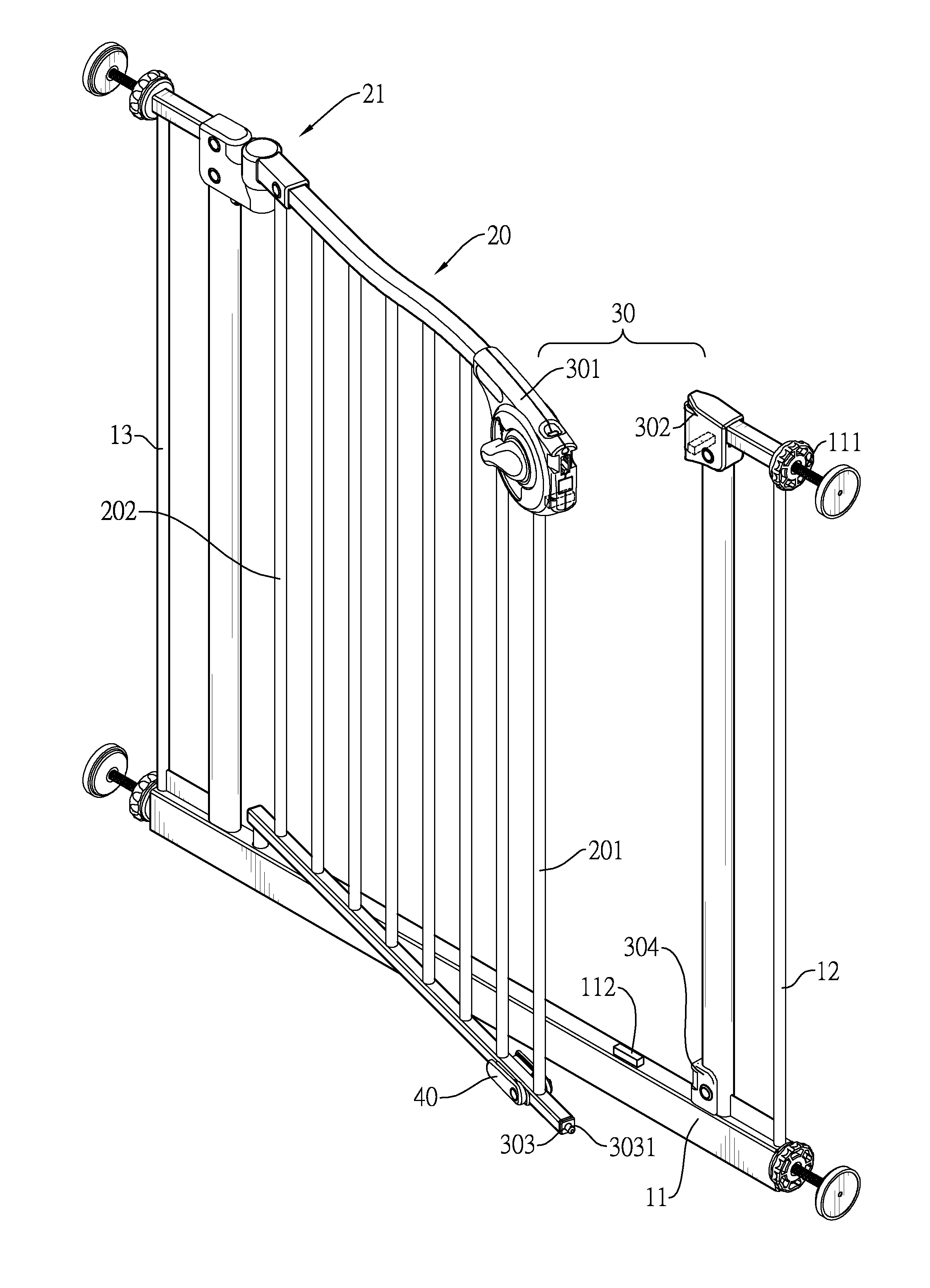
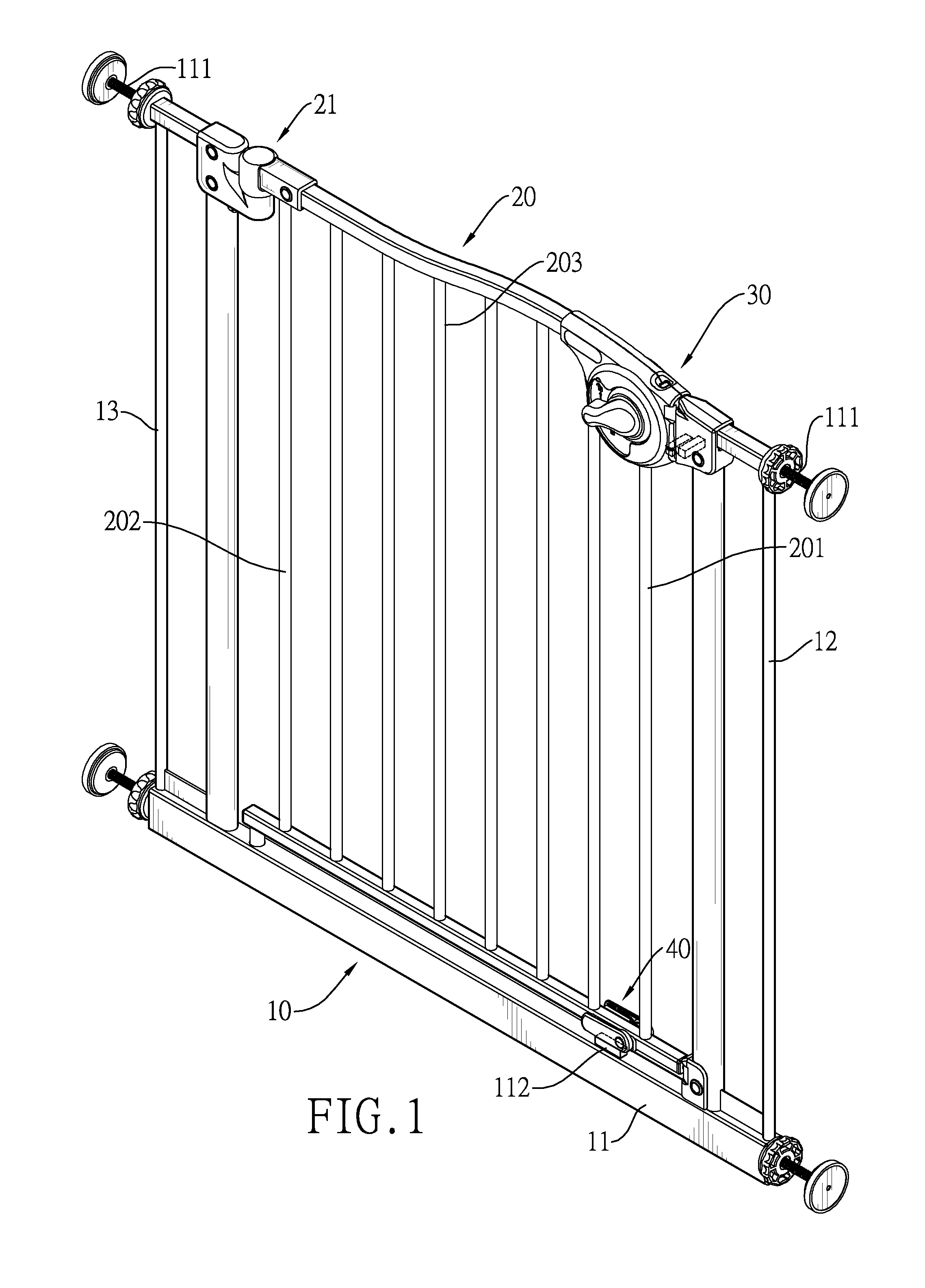
[0026]With reference to FIG. 1, a safety gate in accordance with the present invention has a gate frame 10, a pivotable fence 20, a latch device 30 and a fence stopper 40.

[0027]The gate frame 10 has a base 11, a first side frame 12 and a second side frame 13. The base 11 is elongated and has a block 112. The block 112 is mounted on a top of the base 11. The first side frame 12 and the second side frame 13 are respectively and vertically mounted on two locations of the top of the base 11 adjacent to two ends of the base 11 of the gate frame 10. Each of the first side frame 12 and the second side frame 13 has two contact pads 111. The contact pads 111 are respectively mounted on a top and a bottom of each of the first side frame 12 and the second side frame 13 for the gate frame 10 to be securely mounted on a place, such as an entrance to a kitchen.

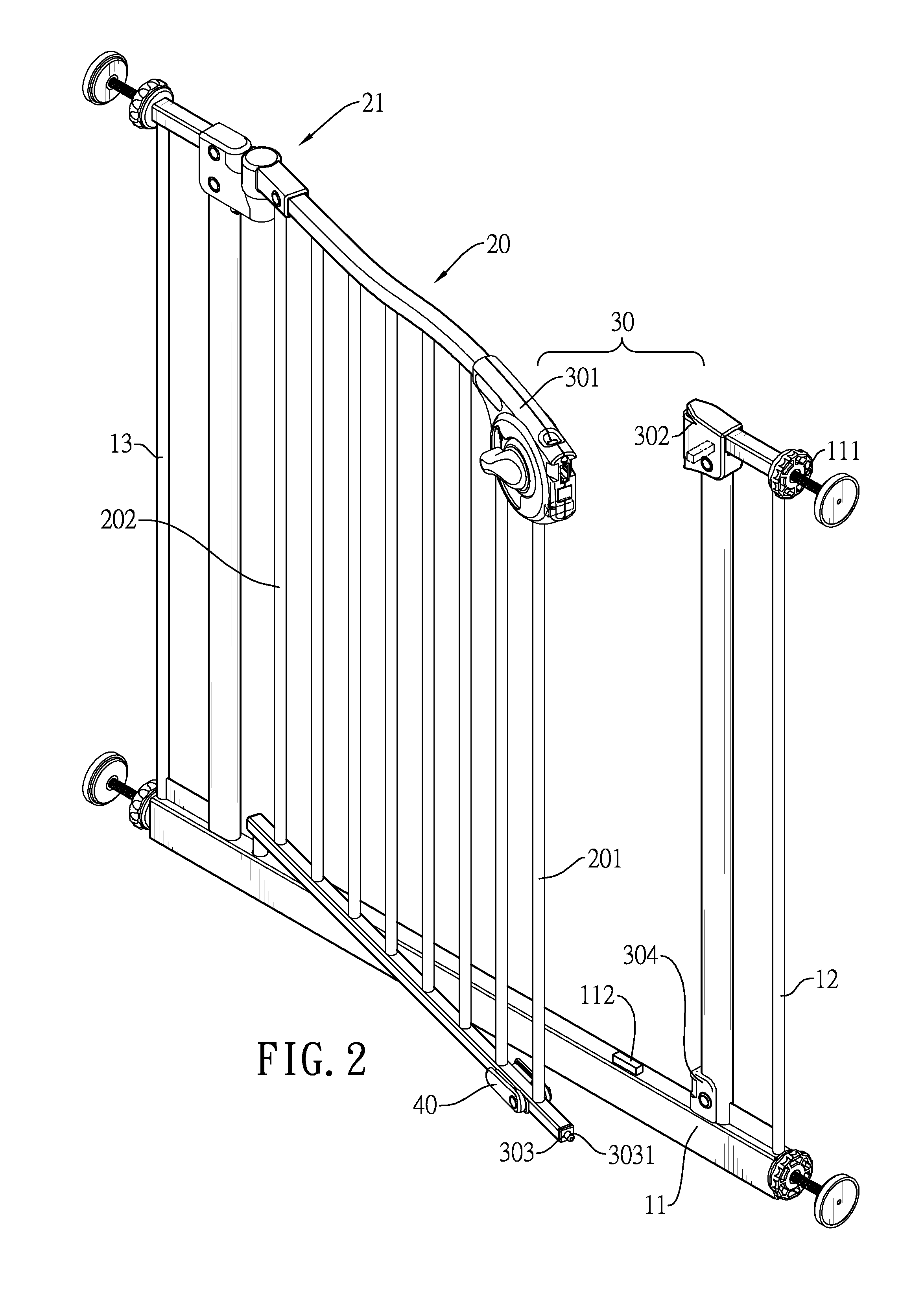
[0028]With reference to FIG. 2, the pivotable fence 20 is pivotally mounted within the first side frame 12, the second side frame 13 and t...


PUM


Abstract

A safety gate has a gate frame, a pivotable fence, a latch device and a fence stopper. The gate frame has a base, two side frames and a block formed on the base. The pivotable fence is mounted within the gate frame. One side of the pivotable fence is pivotally mounted within the gate frame by a pivoting element. The latch device has a first pin member and a first latch member respectively having two magnets corresponding to each other. The fence stopper abuts against the block to limit the pivotable fence to be unidirectionally pivotable. The attraction force between the magnets and a restoring force of the pivoting element return the pivotable fence back within the gate frame. The fence stopper and the block abut against each other to avoid the circumstance when the pivotable fence is slammed too hard and the latch device is not securely locked.

Description

BACKGROUND OF THE INVENTION[0001]1. Field of the Invention[0002]The present invention relates to a safety gate, and more particularly to a safety gate having magnets for facilitating the positioning of the safety gate.[0003]2. Description of the Related Art[0004]Safety gates serve to block young children or pets at the top of stairs for a fall protection or at the entrance to a room or an area, such as kitchen, living room or balcony, to limit the young children or pets to stay in the room or from accessing the room. However, sometime when parents do not lock the safety gate firmly due to carelessness, young children may still be able to pass through an open gap of the unlocked safety gate to enter a dangerous zone. A Chinese Utility Model Application Number 201020139726 entitled “Fence gate having alarm capability” is disclosed to present a color board mounted for alerting purpose on the locking device for the safety gate. The color board displays one color when the safety gate is ...

Claims


Application Information

Patent Timeline
IPC IPC(8): E06B9/02E05B65/06
CPCE05B65/0007E05C1/06E06B2009/002E06B9/04E05C19/16
Inventor WANG, TSUNG-HSIANG
Owner WANG TSUNG HSIANG
Learn More