Filter unit for an extractor hood

Active Publication Date: 2012-10-11
BSH BOSCH & SIEMENS HAUSGERAETE GMBH
View PDF6 Cites 14 Cited by
  • Summary
  • Abstract
  • Description
  • Claims
  • Application Information

AI Technical Summary

Benefits of technology

[0005]It is therefore an object of the present invention to create a filter unit, in particular a perimetric extraction filter, which does not have these disadvantages of the prior art, yet nonetheless provides a reliable form of protection for a baffle plate of the filter element.

Problems solved by technology

For one thing, the weight of the protection plate is heavy on account of said materials.
Another drawback is that in general protection plates made of said materials are not elastically deformable.

Method used


Image

  • Filter unit for an extractor hood
  • Filter unit for an extractor hood
  • Filter unit for an extractor hood

Examples


Embodiment Construction

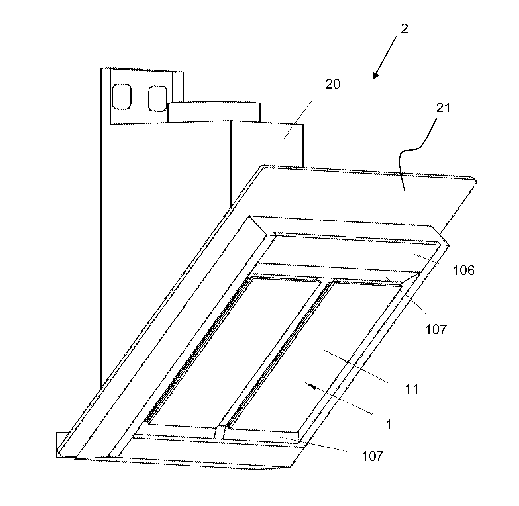
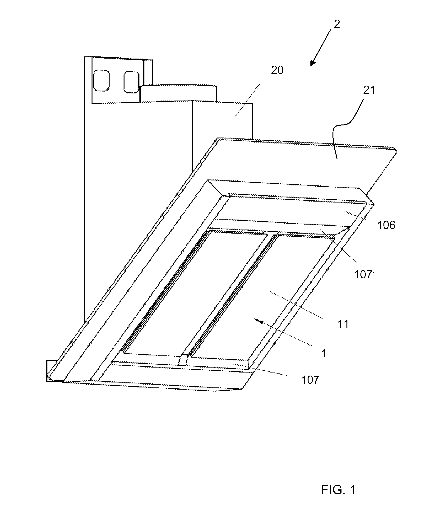
[0035]FIG. 1 shows an extractor hood 2 representing an angled chimney hood. The extractor hood 2 includes a chimney 20 and a viewing hood 21 directed obliquely upward below the chimney 20. Accommodated in the underside of the viewing hood 21 are two filter units 1. Parts of the filter units 1 that can be seen in the view shown in FIG. 1 are in each case the protection plate 11, the frame 106 and the perimetric extraction gap 107.

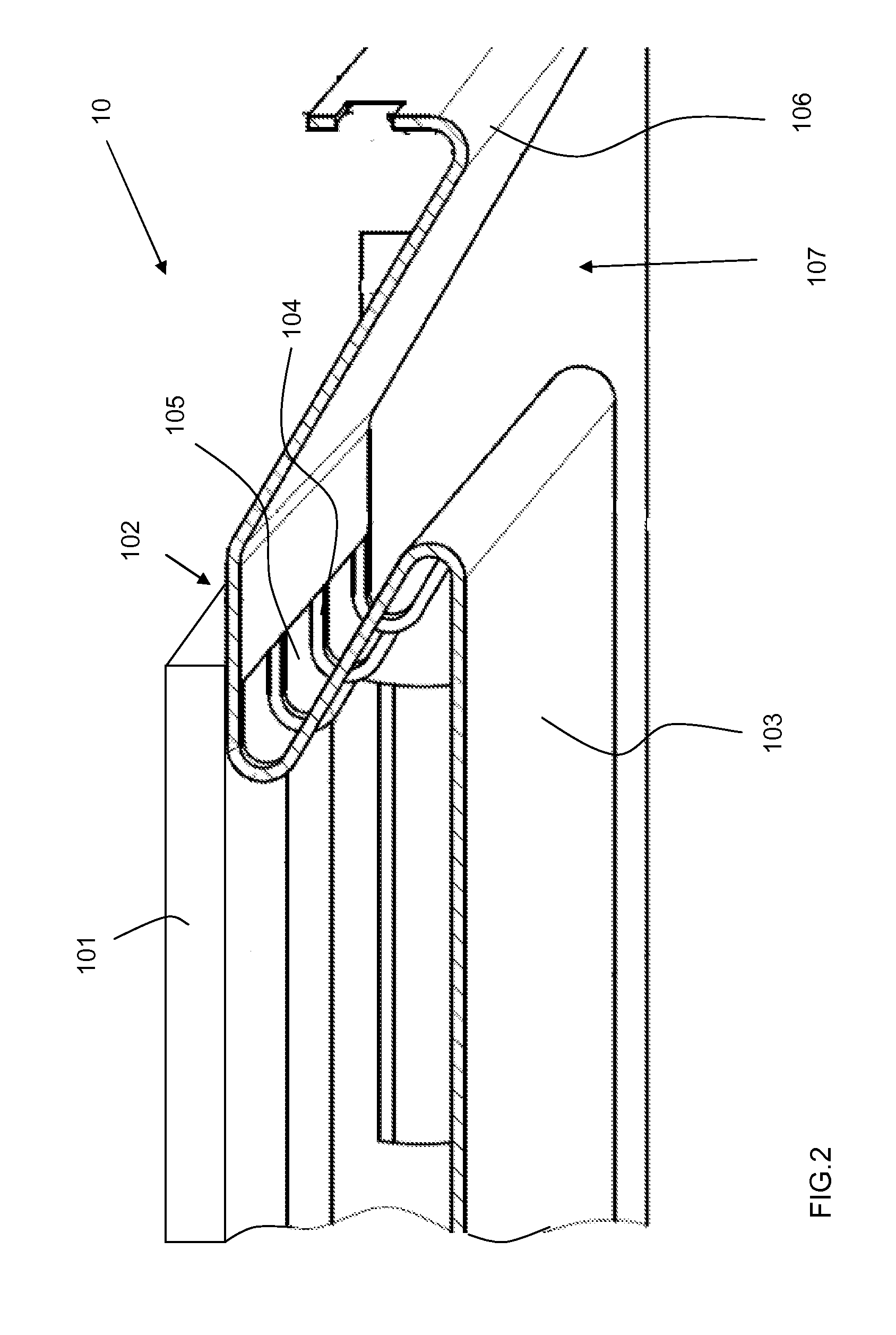
[0036]FIG. 2 shows an embodiment variant of a filter element 10 on which a protection plate (not shown) can be provided. The filter element 10 includes a filter 101 which is retained on a filter retaining fixture 102. The filter retaining fixture 102 comprises a baffle plate 103 which is connected to the region of the filter retaining fixture 102 on which the filter 101 is retained by way of inclined, upward-directed webs 104 between which gaps or apertures 105 exist. Starting from this region a connecting zone extends obliquely downward and transitions into...


PUM

PropertyMeasurementUnit
Thicknessaaaaaaaaaa
Thicknessaaaaaaaaaa
Thicknessaaaaaaaaaa

Abstract

A filter unit for an extractor hood includes at least one filter element, and at least one protection plate which is arranged in a flow direction upstream of the filter element. The protection plate is made of at least two layers and can have a thickness in a range of 0.5 mm to 10 mm.

Description

BACKGROUND OF THE INVENTION[0001]The invention relates to a filter unit for an extractor hood.[0002]Extractor hoods are known in which a plate known as a baffle plate is arranged in front of the actual grease filter, which may be for example a metal mesh filter. The baffle plate is fixed at a defined, sufficiently great distance from the grease filter directly on the viewing hood of the extractor hood. This type of fixture allows the vapor to flow along the edge of the baffle plate and arrive at the grease filter. This achieves the deflection required for cleaning the vapor or, as the case may be, creates the necessary turbulence in the vapor. Filter units in which the vapor is cleaned in this way are also referred to as perimetric extraction filters.[0003]Furthermore, in an earlier application there has been proposed a filter unit for an extractor hood which has at least one filter element which in turn has at least one filter and at least one filter retaining fixture. At least one...

Claims


Application Information

Patent Timeline
IPC IPC(8): B01D50/00
CPCF24C15/2035B01D45/08B01D46/10B01D46/0005B01D45/12B01D50/20
InventorEHRENSBERGER, JULIAGROBLEBEN, RALFKLUNKER, SANDORKOTLINSKI, THOMASKRAEMER, OLIVERMETZ, DANIELORTMANN, CHRISTOPHREIFF, UDOUEBELE, VOLKMAR
OwnerBSH BOSCH & SIEMENS HAUSGERAETE GMBH