
Interrogator and System Employing the Same

Active Publication Date: 2012-10-11
LONE STAR IP HLDG LP
View PDF7 Cites 59 Cited by
  • Summary
  • Abstract
  • Description
  • Claims
  • Application Information

AI Technical Summary

Benefits of technology

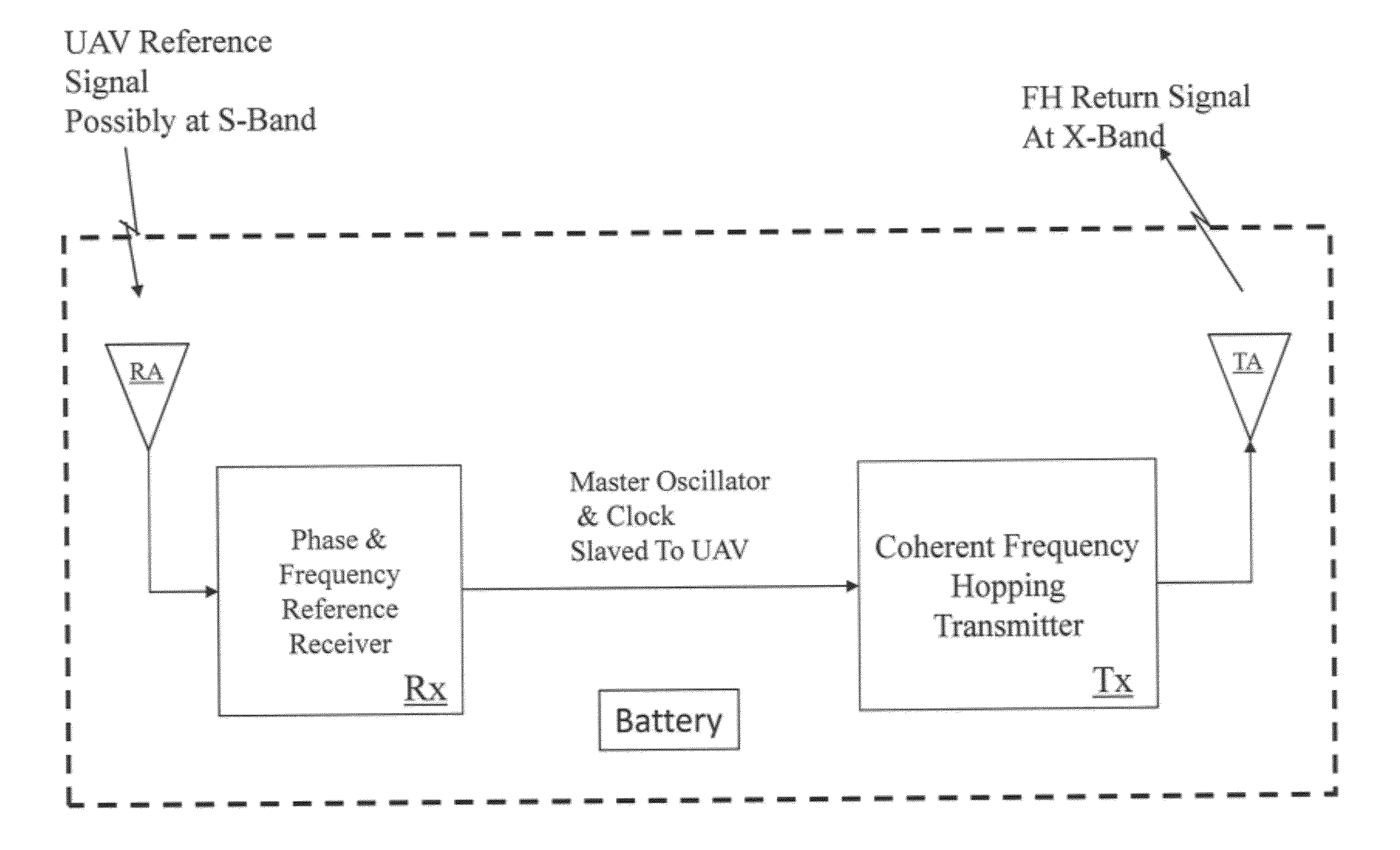
[0005]These and other problems are generally solved or circumvented, and technical advantages are generally achieved, by advantageous embodiments of the present invention, which includes an interrogator and system employing the same. In one embodiment, the interrogator includes a receiver configured

Problems solved by technology

One major weakness with extant RFID systems is their poor sensitivity limiting operation to fairly high signal-to-noise (“SNR”) regimes.

Method used


Image

  • Interrogator and System Employing the Same
  • Interrogator and System Employing the Same
  • Interrogator and System Employing the Same

Examples


Embodiment Construction

[0026]The making and using of the presently preferred embodiments are discussed in detail below. It should be appreciated, however, that the present invention provides many applicable inventive concepts that can be embodied in a wide variety of specific contexts. The specific embodiments discussed are merely illustrative of specific ways to make and use the invention, and do not limit the scope of the invention.

[0027]The present disclosure is related to RFID systems and weapon systems. For exemplary weapons and weapons systems, see U.S. patent application Ser. No. 10 / 841,192 entitled “Weapon and Weapon System Employing The Same,” to Roemerman, et al., filed May 7, 2004, U.S. Pat. No. 7,530,315 entitled “Weapon and Weapon System Employing the Same,” to Tepera, et al., issued May 5, 2009, and U.S. Pat. No. 8,117,955 entitled “Weapon Interface System and Delivery Platform Employing the Same,” to Roemerman, et al., issued Feb. 21, 2012, which are incorporated herein by reference. Additi...


PUM


Abstract

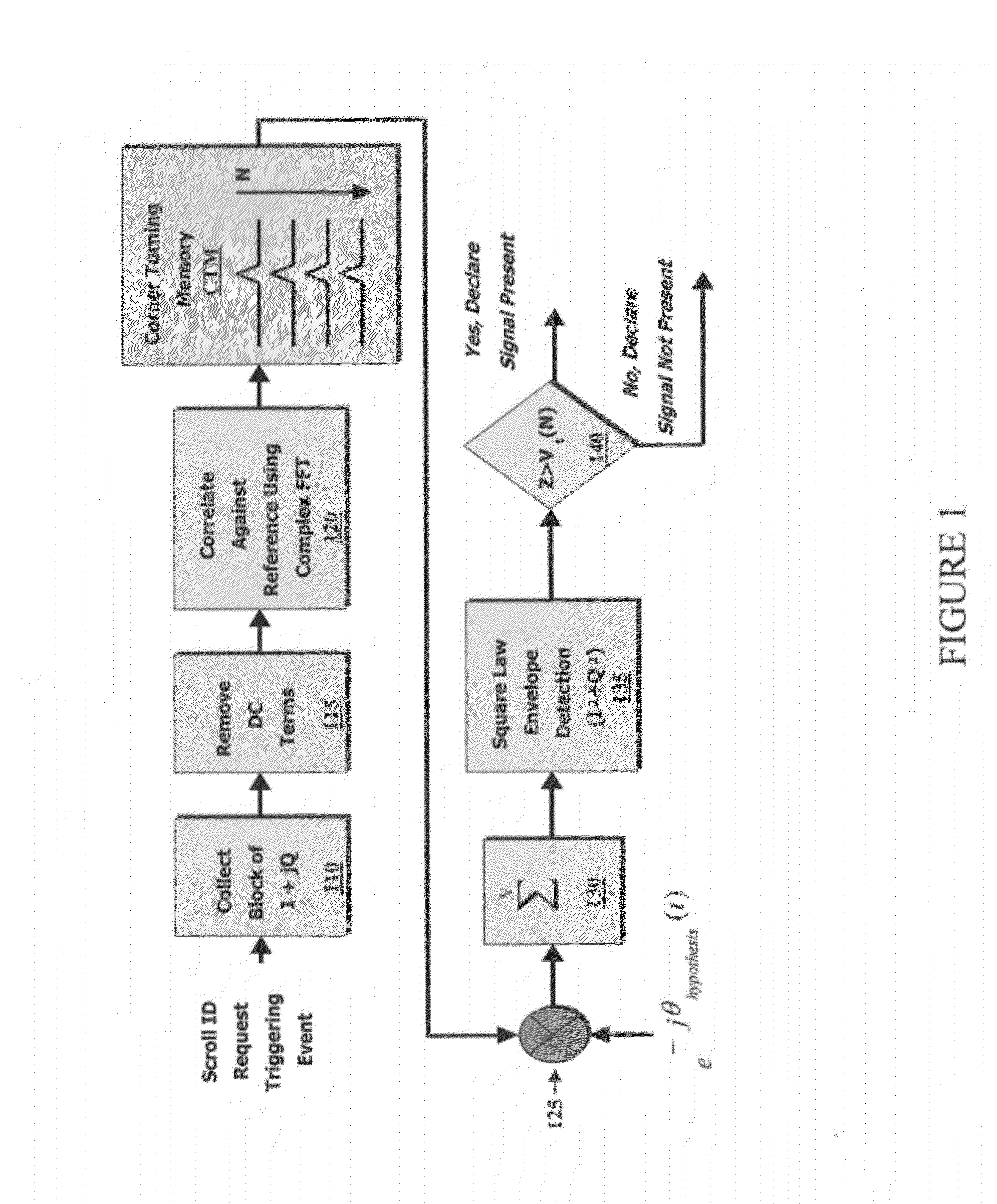
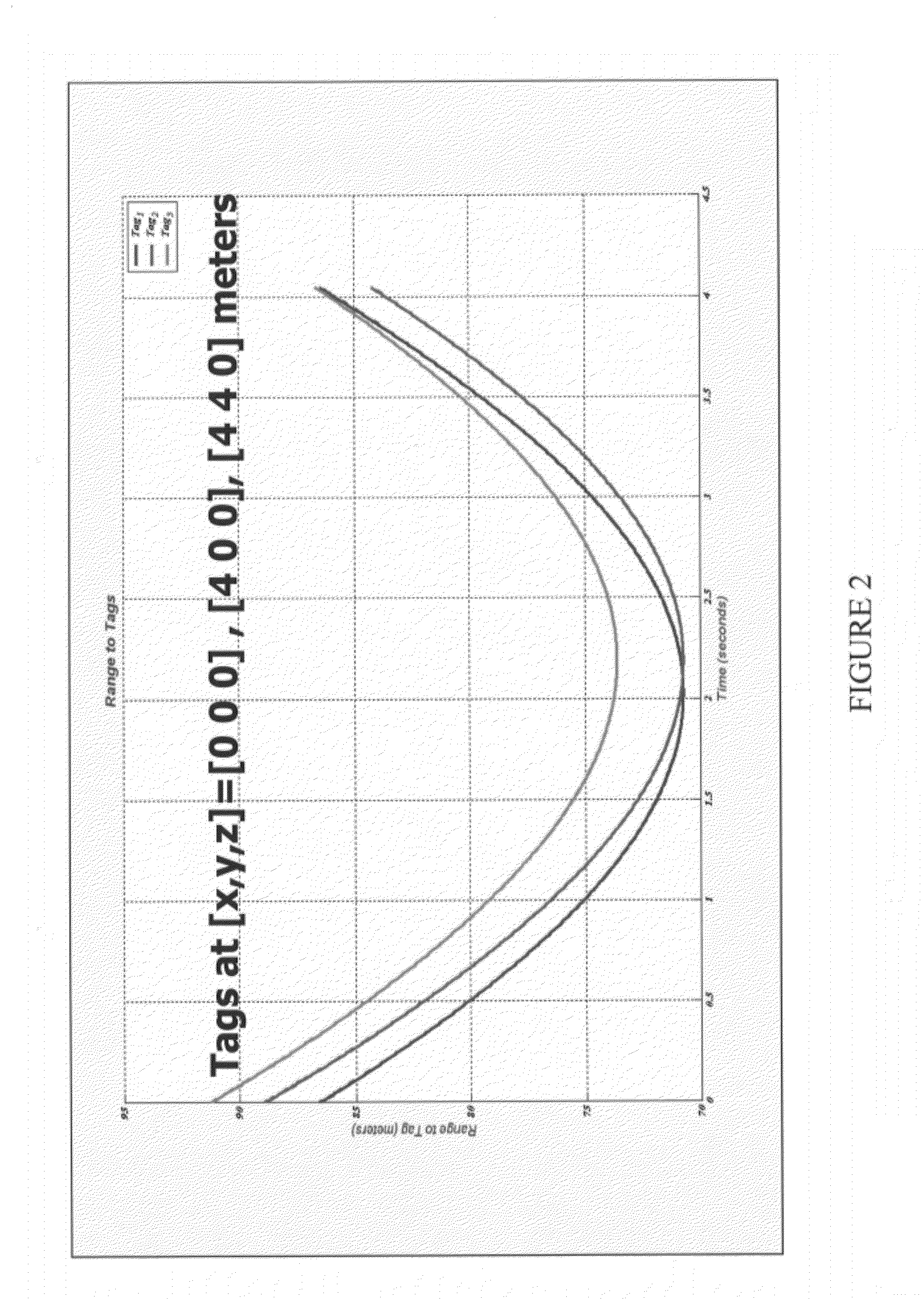
An interrogator and system employing the same. In one embodiment, the interrogator includes a receiver configured to receive a return signal from a tag and a sensing module configured to provide a time associated with the return signal. The interrogator also includes a processor configured to employ synthetic aperture radar processing on the return signal in accordance with the time to locate a position of the tag.

Description

[0001]This application claims the benefit of U.S. Provisional Application No. 61 / 474,056 entitled “Innovative, Novel, and Unconventional Integration of SAR-Like Processing Techniques with RFID,” filed Apr. 11, 2011, which application is incorporated herein by reference.TECHNICAL FIELD[0002]The present invention is directed to radio frequency identification systems and weapon systems, and method of operating the same.BACKGROUND[0003]Radio Frequency Identification (“RFID”) tags are finding wide application in inventory control and tracking systems. In these systems, a two-way communications link is established wherein readers (or interrogators) interrogate RFID tags to respond with their identification and perhaps other ancillary information. The RFID tags can be broadly separated into three categories, namely, active, semi-active and passive. The active RFID tags contain a battery and communicate on the reverse link (RFID tag to reader) using conventional radio frequency (“RF”) commu...

Claims


Application Information

Patent Timeline
IPC IPC(8): G06K7/01
CPCG01S5/0221G01S5/12G01S2013/9064G01S13/9035G01S13/751G01S13/9064G01S13/9004
Inventor SCOTT, HUGH LOGANROEMERMAN, STEVEN D.VOLPI, JOHN P.
Owner LONE STAR IP HLDG LP
Learn More