Pulse compression radar

a pulse compression and radar technology, applied in the field of pulse compression radar, can solve the problem of limited bandwidth increas

Inactive Publication Date: 2000-05-23
ALCATEL LUCENT SAS
View PDF7 Cites 48 Cited by
  • Summary
  • Abstract
  • Description
  • Claims
  • Application Information

AI Technical Summary

Benefits of technology

The invention applies not only to pulse compression radar but also to radar coherent over a plurality of pulses, such as synthetic aperture radar (SAR). In the foregoing description and in the following description the term "pulse compression radar" must be understood as referring not only to radar of this type but also to coherent radar in which the received signal is subject to frequency variation (linear or otherwise) pulse by pulse, as is the case with the Doppler effect in synthetic aperture radar during passage of the echo transversely to the antenna lobe as a consequence of movement of the moving body carrying the radar. In this latter case the distortion measured by the calibration pulse consists in the errors occurring during the integration time for a plurality of pulses.

Problems solved by technology

The bandwidth increase must be limited because it increases the noise band and degrades the signal to noise ratio commensurately.

Method used


Image

  • Pulse compression radar
  • Pulse compression radar
  • Pulse compression radar

Examples


Embodiment Construction

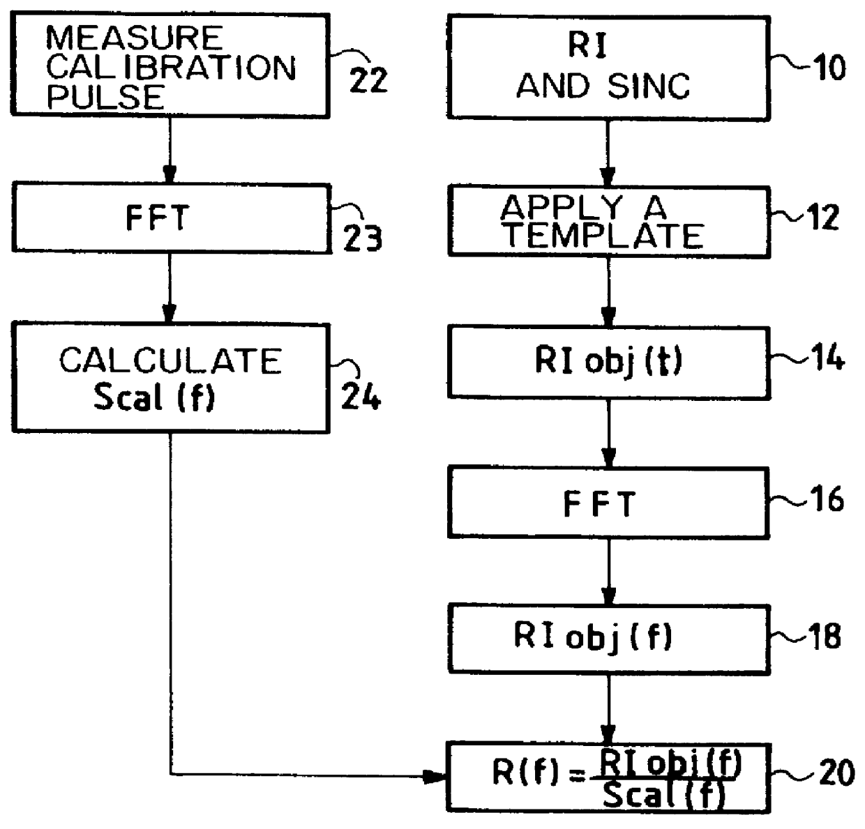
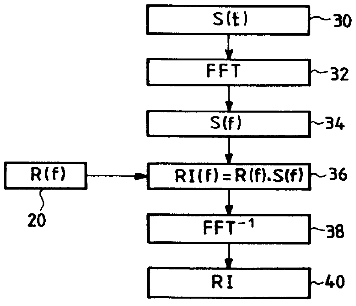
The frequency reference R(f) which will be used in the compression filter and which is characterized by a complex function of the frequency f is synthesized by the method shown in FIG. 1.

To this end, the starting point (block 10) is a conventional (possibly weighted) sinc function impulse response, for example, which corresponds to a transmitted signal without distortion whose frequency varies as a linear function of time, i.e. an ideal "chirp". This conventional impulse response, which is a function of time, is a digital signal.

Next (block 12), a template is applied to the conventional impulse response with the aim of attenuating the secondary, far and diffuse lobes in accordance with the accuracy required of the radar.

FIG. 4 shows an illustrative example of a template indicating the objective with an impulse response whose main lobe is that of the ideal impulse response (RI) in terms of sinc(t) (sinc function) and whose secondary lobes are equal to those in terms of sinc(t) less 2...


PUM


Abstract

The invention concerns a method of synthesizing a replica used in the compression filter of pulse compression radar. The replica is calculated from the spectrum of a required impulse response. The required impulse response is preferably obtained from an analytical function, such as a sinc function or a weighted sinc function, and a template. It is preferable to use calibration signals of the instrument to calculate the replica. The invention also applies to synthetic aperture radar.

Description

The invention concerns pulse compression radar.In radar of this type the frequency of the wave transmitted towards the target varies as a function of time, for example in a linear fashion. To avoid degrading the distance resolution on reception, the wave is time compressed. The filter applying this compression uses a signal which is often called a "replica".The replica determines the performance of the radar, which is usually characterized by its impulse response. Impulse response is the response of the instrument when the signal is transmitted towards an isolated point target, without interference. Impulse response in the time domain RI(t) has the value:RI(t)=s(t)*r(t),where S(t) is the transmitted signal as a function of time, r(t) is the replica and * is the convolution product.In the frequency domain:RI(f)=S(f).multidot.R(f)where S(f)=F(s(t)) is the spectrum of the transmitted signal and R(f)=F(r(t)) is the spectrum of the replica.In the conventional case of a matched filter, wh...

Claims


Application Information

Patent Timeline
Patent Type & Authority Patents(United States)
IPC IPC(8): G01S13/00G01S13/28G01S7/40G01S13/90
CPCG01S7/4052G01S13/282G01S2007/4082G01S13/90G01S7/4082
Inventor FAURE, ALAINSUINOT, NOEL
Owner ALCATEL LUCENT SAS
Why Eureka
Try Eureka