Three-dimensional synthetic aperture radar for mine detection and other uses

a synthetic aperture radar and mine detection technology, applied in the field of three-dimensional imaging, can solve the problems of affecting reducing the detection accuracy of radars, so as to achieve enhanced image resolution

Inactive Publication Date: 2006-01-03
NAVY USA AS REPRESENTED BY THE SEC OF THE THE
View PDF18 Cites 45 Cited by
  • Summary
  • Abstract
  • Description
  • Claims
  • Application Information

AI Technical Summary

Benefits of technology

[0013]An advantage of the present invention concerns the use of an aerial translatable three-dimensional synthetic aperture radar for the detection of buried objects such as mines.
[0014]An additional advantage of the present invention concerns enhanced image resolution compared with conventional SAR systems by implementing SAR using a radar signal having a frequency of at least thre

Problems solved by technology

Buried mines on, e.g., a beachhead, are a major threat to amphibious landing forces and a severe obstacle to a rapid amphibious landing.
Clearing mines prior to a full-scale landing is a slow and tedious process that requires manual location and neutralization of the individual mines.
One disadvantage with current radar-based mine detecting systems is that these systems tend to be limited to generating only a two-dimensional image rather than a three-dimensional image.
A two-dimensional imaging syst

Method used


Image

  • Three-dimensional synthetic aperture radar for mine detection and other uses
  • Three-dimensional synthetic aperture radar for mine detection and other uses
  • Three-dimensional synthetic aperture radar for mine detection and other uses

Examples


Embodiment Construction

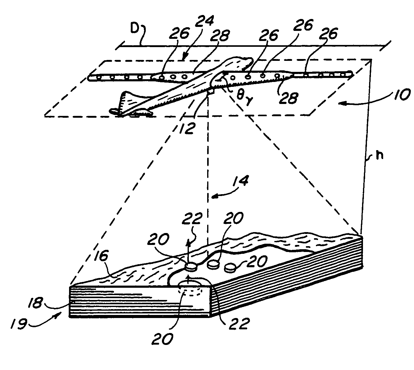
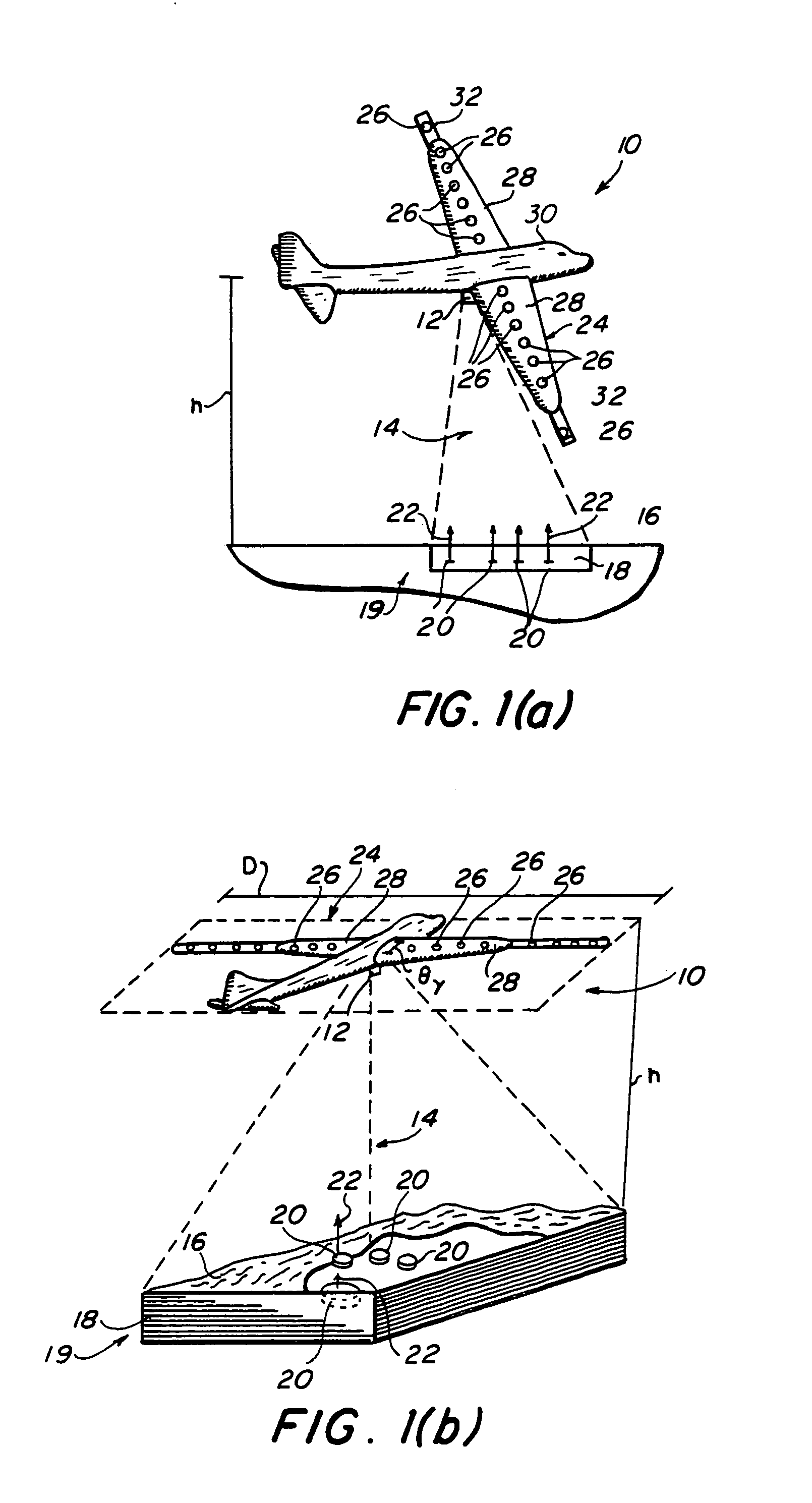
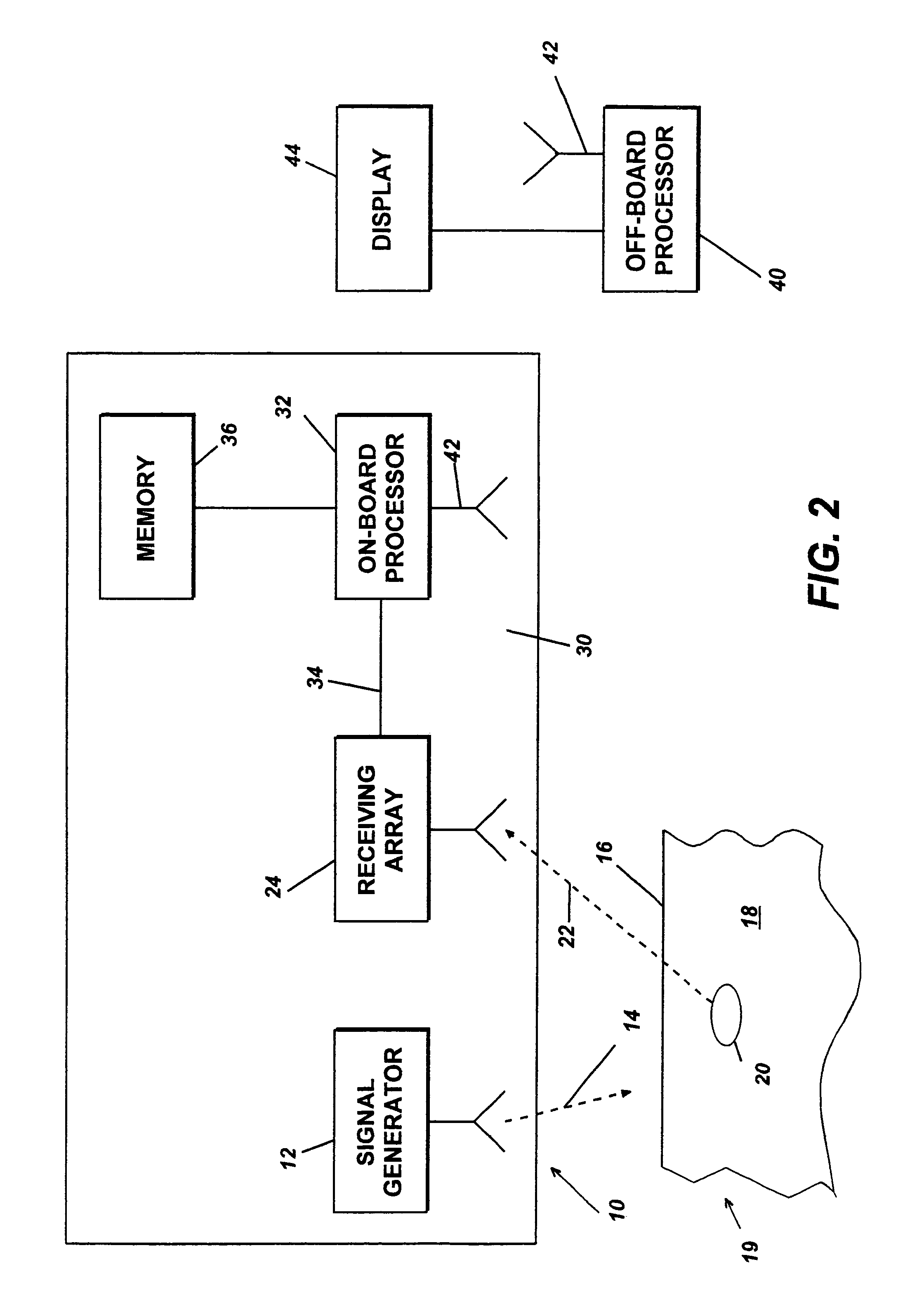
[0020]Referring now to the drawings, and in particular to FIGS. 1(a) and 1(b), illustratively depicted therein is radar system 10 according to the present invention. Radar system 10 includes radar transmitter 12 which generates radar signal 14 of at least three gigahertz, corresponding to the S-band and X-band carrier frequencies. Preferably, the frequency is within the range of three to ten gigahertz to provide good resolution with acceptable signal attenuation. However, higher frequencies can be used to provide enhanced resolution where signal attenuation is accommodated.

[0021]The radar signal 14 is directed towards the surface 16 of the underlying ground 18 of a target area denoted 19. Radar signal 14 penetrates surface 16 and reflected signals 22 are produced by the radar signal 14 reflecting off of the surface of buried objects indicated at 20.

[0022]An antenna array 24 is formed of a plurality of receiving antennas 26 which receive reflected signal 22. Receiving antennas 26 are...


PUM


Abstract

A radar system for generating a three-dimensional image includes a radar transmitter which is operable to produce a radar signal of a frequency of at least three gigahertz. A plurality of radar receiving antennas from an antenna array. The antenna array is aerially translatable. For example, in one embodiment, the antenna array is disposed along the wings of an aircraft which, in operation, flies over the intended target area. A three-dimensional image is generated from a reflected radar signal returned from the surface of an object in response to the transmitted radar signal. The radar system may be incorporated into an aircraft and adapted to detect subsurface objects such as mines buried beneath the surface of the ground as the aircraft traverses over a target area.

Description

BACKGROUND OF THE INVENTION[0001]1. Field of the Invention[0002]The present invention relates to a system and method for detecting objects under the surface of the ground, and in particular, to three-dimensional imaging to detect an underground target item such as a mine.[0003]2. Background of the Invention[0004]Buried mines on, e.g., a beachhead, are a major threat to amphibious landing forces and a severe obstacle to a rapid amphibious landing. Clearing mines prior to a full-scale landing is a slow and tedious process that requires manual location and neutralization of the individual mines. This process includes the use of heavy machinery to detonate anti-personnel mines while, at the same time, facing the threat of larger anti-tank mines.[0005]Ground penetration radar systems using transistor generated short pulses have been in use for decades for geophysical applications. These systems can be relatively compact, approximately the size of a lawn mower, and are generally pulled al...

Claims


Application Information

Patent Timeline
IPC IPC(8): G01S13/00F41H11/12
CPCF41H11/12
Inventor TEMES, CLIFFORD L.PAVCO, JOHN A.
Owner NAVY USA AS REPRESENTED BY THE SEC OF THE THE
Why Eureka
Try Eureka