Multocular image pickup apparatus and multocular image pickup method

a pickup method and multi-ocular technology, applied in image acquisition, television systems, instruments, etc., can solve the problems of deteriorating image quality in the high-definition synthesized image, inability to obtain corresponding points, and difficulty in achieving compactness and thinness, so as to reduce the deterioration of image quality, improve the appearance of the overall high-definition synthesized image, and increase the processing amount

Active Publication Date: 2012-10-18
SHARP KK
View PDF9 Cites 203 Cited by
  • Summary
  • Abstract
  • Description
  • Claims
  • Application Information

AI Technical Summary

Benefits of technology

[0027]According to the present invention, in high-definition synthesis processing using two or more cameras, it is possible to achieve suppression of the deterioration of image quality in an occlusion region or a corresponding point detection error region in which corresponding points cannot be found, without increasing the amount of processing. Additionally, it is possible to achieve the effect of rendering a region in which high definition was not possible because of failure to detect corresponding points in a manner that approaches the visual psychological effect as when seen by the left and right human eyes, thereby improving the appearance of the overall high-definition synthesized image.

Problems solved by technology

This has been accompanied by the image pickup apparatus increasing in size, leading to the problem of difficulty in achieving compactness and thinness.
However, because of the occurrence of regions that can be photographed from one of the cameras but that cannot be photographed in what is called an occlusion, being hidden from the other camera behind an object, there are cases in which corresponding points cannot be obtained.
There is the problem that, this occlusion region, because of erroneous searching for corresponding points, leads to a deterioration in image quality in the high-definition synthesized image.

Method used


Image

  • Multocular image pickup apparatus and multocular image pickup method
  • Multocular image pickup apparatus and multocular image pickup method
  • Multocular image pickup apparatus and multocular image pickup method

Examples


first embodiment

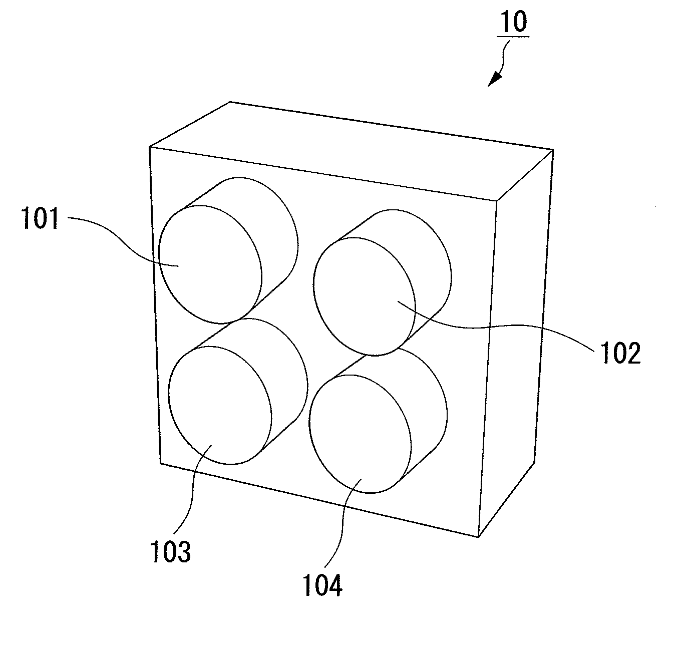
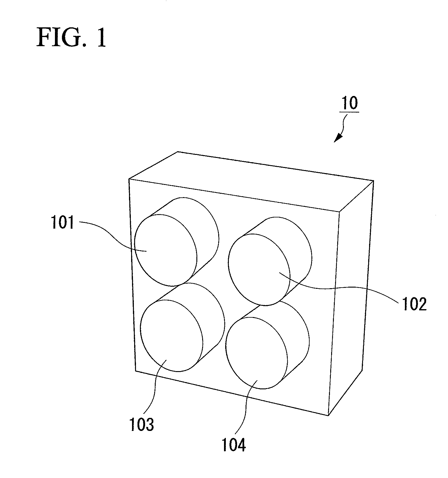
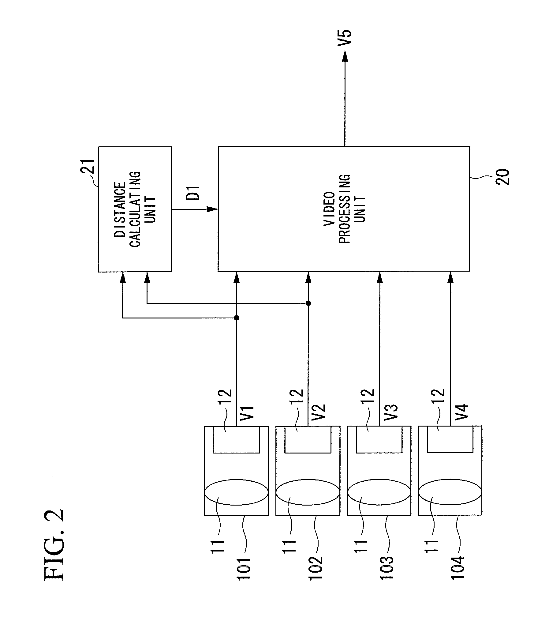
[0049]The multocular imaging apparatus according to the first embodiment of the present invention will be described below, with references made to the drawings. FIG. 1 is a conceptual drawing of a multocular imaging apparatus according to the first embodiment of the present invention. FIG. 2 is a block diagram of the multocular imaging apparatus according to the same embodiment. As shown in FIG. 1, the multocular imaging apparatus 10 of the present embodiment has four sets of image pickup units 101, 102, 103, and 104. Each of the image pickup units 101, 102, 103, and 104 has an imaging lens 11 and an imaging element 12. The imaging lenses 11 form the light from the captured object onto the imaging elements 12, and the formed image is photoelectric converted by the imaging elements 12, for example, a CMOS imaging element or the like, and is output as video signals V1, V2, V3, and V4. By capturing by each of the four sets of image pickup units 101, 102, 103, and 104, the video signals...

second embodiment

[0072]Next, referring to FIG. 15 and FIG. 16, the second embodiment of the present invention will be described. FIG. 15 is a block diagram showing the constitution of a multocular imaging apparatus according to the second embodiment. FIG. 16 is a block diagram showing the constitution of the distance calculating unit 151 shown in FIG. 15. In the multocular imaging apparatus 10 shown in FIG. 15, parts that are the same as in the multocular imaging apparatus 10 shown in FIG. 2 are assigned the same reference symbols and the descriptions thereof are omitted herein. The point of difference in the multocular imaging apparatus shown in FIG. 15 with respect to the multocular imaging apparatus 10 shown in FIG. 2 is that, rather than the distance calculating unit 21, it is provided with a distance calculating unit 151. The parallax data D11 that the distance calculating unit 151 outputs is sent to the video processing unit 20 shown in FIG. 15. Because, the video processing unit 20 shown in F...


PUM


Abstract

A multocular image pickup apparatus includes: a distance calculation unit that calculates information regarding the distance to a captured object from an output video of a first image pickup unit, which is to be the reference unit of a plurality of image pickup units that pick up images, and from an output video of an image pickup unit that is different from the first image pickup unit; a multocular video synthesizing unit that generates synthesized video from the output video of the plurality of image pickup units based on the distance information for regions where the distance information could be calculated; and a monocular video synthesizing unit that generates synthesized video from the output video of the first image pickup unit for regions where the distance information could not be calculated. The distance calculation unit calculates a first distance information that is the distance to the captured object from the output video of the first image pickup unit and the output video of a second image pickup unit that is different from the first image pickup unit, and in case that there is a region where the first distance information could not be calculated, for the region where the first distance information could not be calculated, the distance calculation unit recalculates information regarding the distance to the captured object from the output video of an image pickup unit that was not used for calculating the distance among the plurality of image pickup units, and from the output video of the first image pickup unit.

Description

TECHNICAL FIELD[0001]The present invention relates to a multocular image pickup apparatus and a multocular image pickup method.[0002]Priority is claimed based on the Japanese patent application 2009-291624, filed on Dec. 24, 2009, the content of which is incorporated herein by reference.BACKGROUND ART[0003]In recent years, digital still cameras and digital video cameras (hereinafter referred to as digital cameras) with high image quality have seen rapid growth in use. Digital cameras are also, in parallel with this, advancing in compactness and light weight, and compact digital cameras with high image quality have come to be incorporated into cellular telephone handsets and the like. Image pickup apparatuses, a typical form of which is a digital camera, include a lens optical system, which forms an image, and imaging elements, which photoelectric convert light formed as an image so as to output electrical signals. T he imaging elements used are electronic devices such as CMOS (compl...

Claims


Application Information

Patent Timeline
Patent Type & Authority Applications(United States)
IPC IPC(8): H04N5/262
CPCG06T7/0075H04N5/2258H04N5/232H04N2013/0088H04N5/265G06T1/0007H04N13/0242H04N5/23232G06T7/593H04N13/243H04N23/45H04N23/951H04N25/41
Inventor SHIMURA, TOMOYATANAKA, SEIICHI
Owner SHARP KK
Why Eureka
Try Eureka