Apparatus and method for detecting signal in spatial multiplexing system

a spatial multiplexing and signal detection technology, applied in the field of apparatus and a method for detecting signals in a spatial multiplexing system, can solve the problems of exponential increases in computational complexity, poor performance compared to optimal signal detection techniques, and difficult to use mimo technology for the up-link of a mobile terminal. achieve the effect of no large differences in error performan

Inactive Publication Date: 2012-10-18
CHUNG ANG UNIV IND ACADEMIC COOP FOUND
View PDF1 Cites 8 Cited by
  • Summary
  • Abstract
  • Description
  • Claims
  • Application Information

AI Technical Summary

Benefits of technology

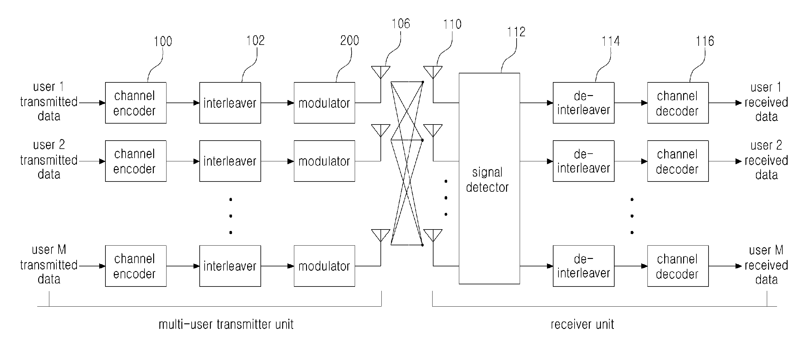
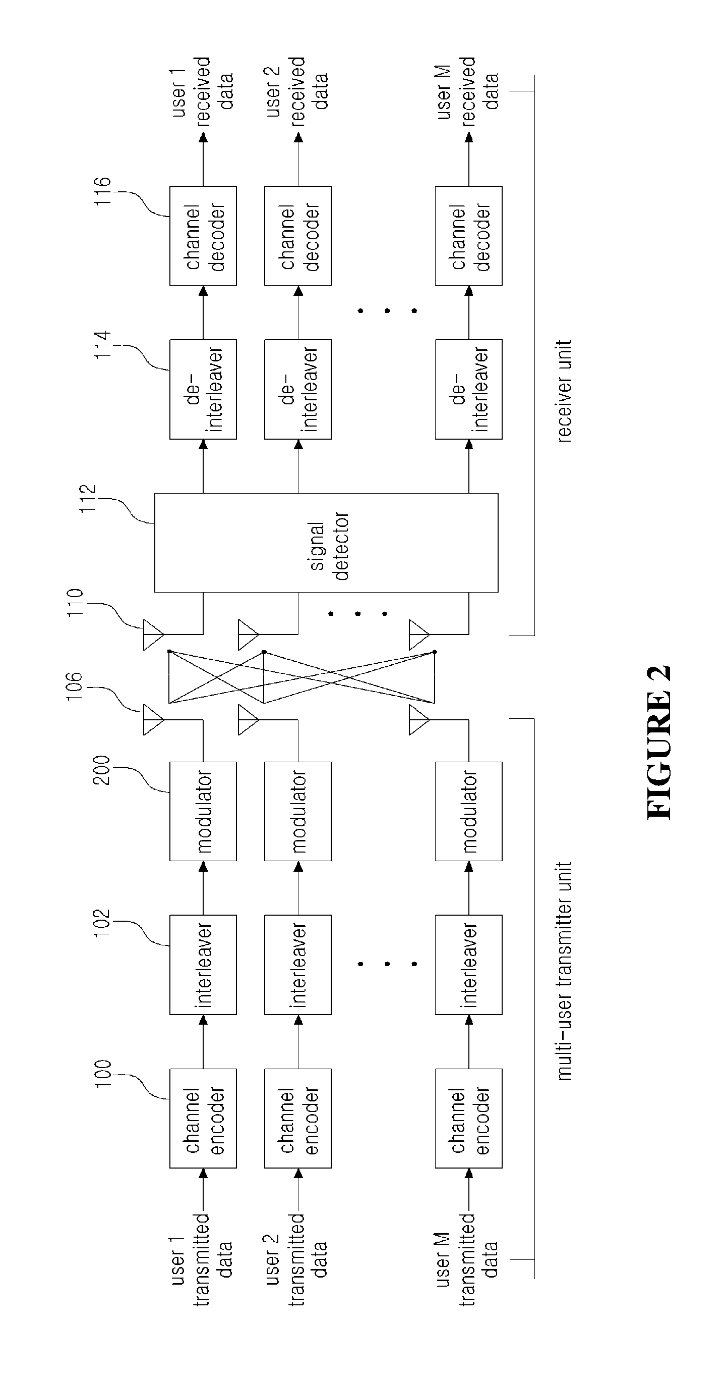
[0013]To resolve the problems in the related art described above, an aspect of the present invention is to propose an apparatus and a method for detecting signals in a spatial multiplexing system with which there are no large differences in error performance generated during the signal detection of data streams at the receiver unit equipped with multiple antennas, when the data streams are transmitted by spatial multiplexing from a single transmitter unit having multiple antennas or from multiple transmitter units equipped with at least one antenna.

Problems solved by technology

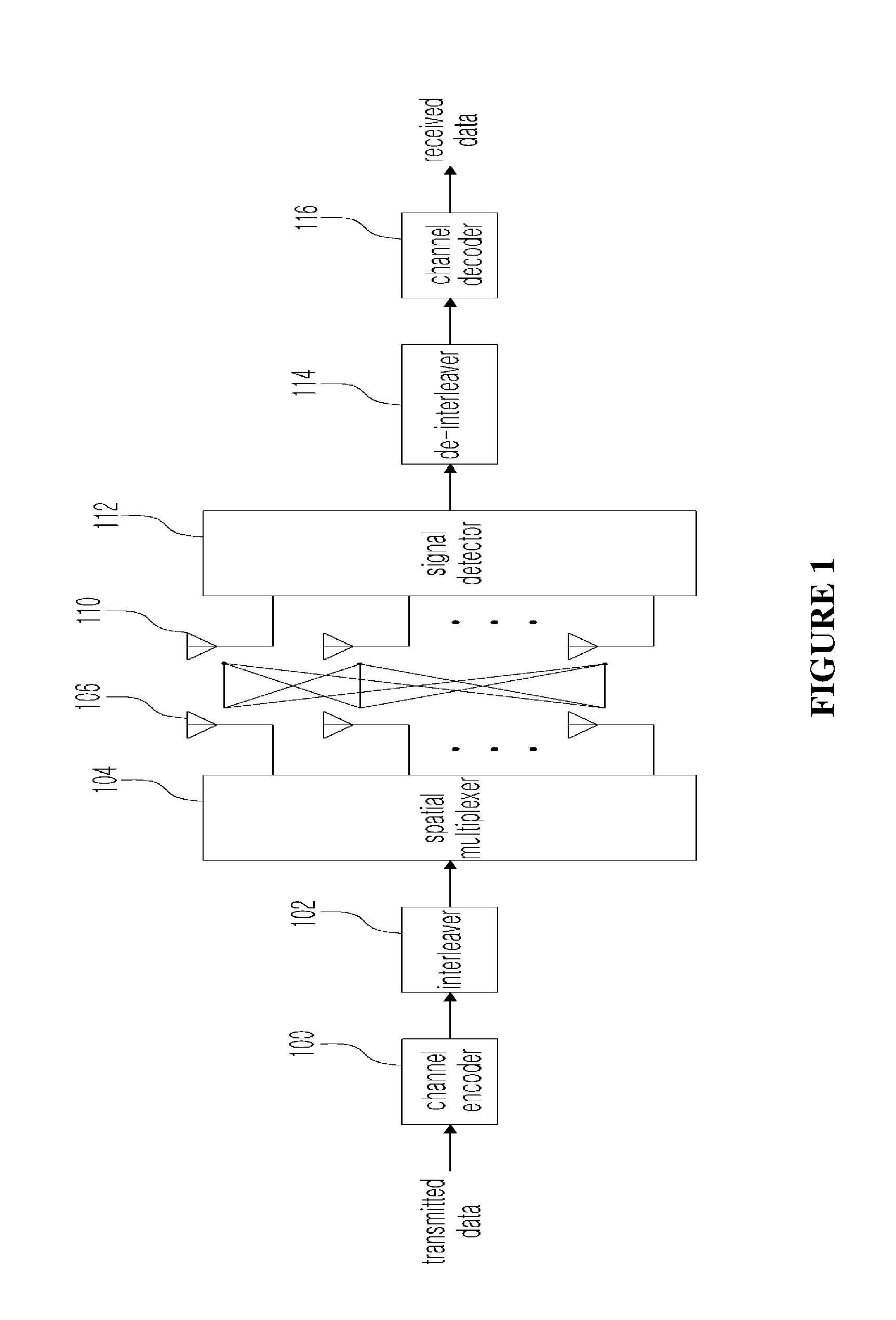
However, since MIMO technology requires multiple antennas in the transmitter and is difficult to apply when the transmission power is low, it was not easy to use the MIMO technology for the up-link of a mobile terminal.
ZF (zero-forcing) and MMSE (minimum mean square error) signal detection techniques, which are linear signal detection techniques, entail a low level of computational complexity and thus can be implemented in relatively simpler structures, but provide much lower performance compared to optimal signal detection techniques.
As such, increases in the number of transmitted data streams and in the order of modulation result in exponential increases in computational complexity, and hence these techniques entail very high computational complexity.
While this can significantly reduce the average complexity compared to the ML technique, it is a depth-first searching method, so that the maximum complexity cannot be predicted, and it is difficult to apply in real-life implementations.
While this technique can provide almost the same level of performance as the ML signal detection technique if there are a sufficient number of candidate vectors, the performance is greatly reduced if there are a small number of candidate vectors.
Among the existing signal detection methods described above, non-linear detection techniques of the OSIC type and quasi-optimal signal detection techniques such as QRM-MLD and SD may entail differences in performance between different data streams, due to error propagation in the signal detection process, limitations concerning the substituted symbols, or limitations concerning the symbol candidate vectors.
In the case of OSIC type signal detection techniques, when a previously detected symbol was erroneously detected in a process involving sequential detection of signals, error propagation may occur.
This may cause a difference in signal detection performance between data streams.
Thus, similar to the OSIC technique, differences in signal detection performance may occur between data streams for SD and QRM-MLD as well.
Signal detection techniques that generate such phenomena are unsuitable for application to collaborative spatial multiplexing.
As described above, a multi-user MIMO system planning to use collaborative spatial multiplexing in its up-link is configured such that the error performance is similar for each user in consideration of the users' channel environments and QoS, but if an existing signal detection method were to be used which generates large differences in signal detection performance between data streams, then the configuration of MCS level would be useless.
As such, existing non-linear detection techniques of the OSIC type and quasi-optimal signal detection techniques such as QRM-MLD, SD, etc., in which the error performances between data streams are affected by error propagation during the signal detection process and limitations in the signal detection algorithms, are not suitable for a multi-user MIMO system using collaborative spatial multiplexing.

Method used


Image

  • Apparatus and method for detecting signal in spatial multiplexing system
  • Apparatus and method for detecting signal in spatial multiplexing system
  • Apparatus and method for detecting signal in spatial multiplexing system

Examples


Embodiment Construction

[0047]As the present invention allows for various changes and numerous embodiments, particular embodiments will be illustrated in the drawings and described in detail in the written description. However, this is not intended to limit the present invention to particular modes of practice, and it is to be appreciated that all changes, equivalents, and substitutes that do not depart from the spirit and technical scope of the present invention are encompassed in the present invention. In describing the drawings, like numerals are used to refer to like elements.

[0048]Unless otherwise defined, all terms used herein, including technical or scientific terms, have the same meanings as those generally understood by those with ordinary knowledge in the field of art to which the present invention pertains. Such terms as those defined in a generally used dictionary are to be interpreted to have the meanings equal to the contextual meanings in the relevant field of art, and are not to be interpre...


PUM


Abstract

Disclosed are an apparatus and a method for detecting signals in a spatial multiplexing system. An embodiment of the invention provides a signal detection apparatus for a single receiver unit equipped with a plurality of antennas in a system having at least one transmitter unit configured to transmit data streams by spatial multiplexing, where the signal detection apparatus includes: a partial linear coefficient generator unit configured to generate a linear weighting matrix by using a preset algorithm on a channel matrix formed between the transmitter unit and the single receiver unit; a partial symbol remover unit configured to generate a first symbol vector by removing all transmittable symbols for each transmitting antenna from all received data streams; and a partial symbol detector unit configured to generate a transmission symbol candidate vector by using the linear weighting matrix and the first symbol vector.

Description

CROSS-REFERENCE TO RELATED APPLICATIONS[0001]This application is a continuation of PCT / KR2010 / 007217 filed on Oct. 21, 2010, which claims priority to Korean Patent Application No. 10-2009-0100408 filed on Oct. 21, 2009, which applications are incorporated herein by reference.TECHNICAL FIELD[0002]The present invention relates to an apparatus and a method for detecting signals in a spatial multiplexing system, more particularly to an apparatus and a method for detecting signals which lower complexity without incurring large differences in error performance, even when using a single receiver unit to receive a multiple number of different data streams transmitted by spatial multiplexing.BACKGROUND ART[0003]In order to maximize spectrum efficiency and transmission speed in a wireless communication system, there is an on-going effort to apply MIMO (multi-input multi-output) technology to systems. There have been many cases recently in which MIMO technology hitherto mentioned only in theor...

Claims


Application Information

Patent Timeline
Patent Type & Authority Applications(United States)
IPC IPC(8): H04B7/02
CPCH04B7/0434H04B7/0848H04B7/0697H04B7/0617H04B7/08
Inventor CHO, YONG-SOOIM, TAE-HO
Owner CHUNG ANG UNIV IND ACADEMIC COOP FOUND
Why Eureka
Try Eureka