
Aircraft vertical trajectory optimization method

a vertical trajectory and optimization method technology, applied in the field of aircraft flight management system, can solve the problems of increasing complexity of conventional methods, affecting the efficiency of aircraft flight, so as to achieve the effect of optimizing fuel and time costs

Inactive Publication Date: 2012-10-18
UNIVERSAL AVIONICS SYST
View PDF10 Cites 36 Cited by
  • Summary
  • Abstract
  • Description
  • Claims
  • Application Information

AI Technical Summary

Benefits of technology

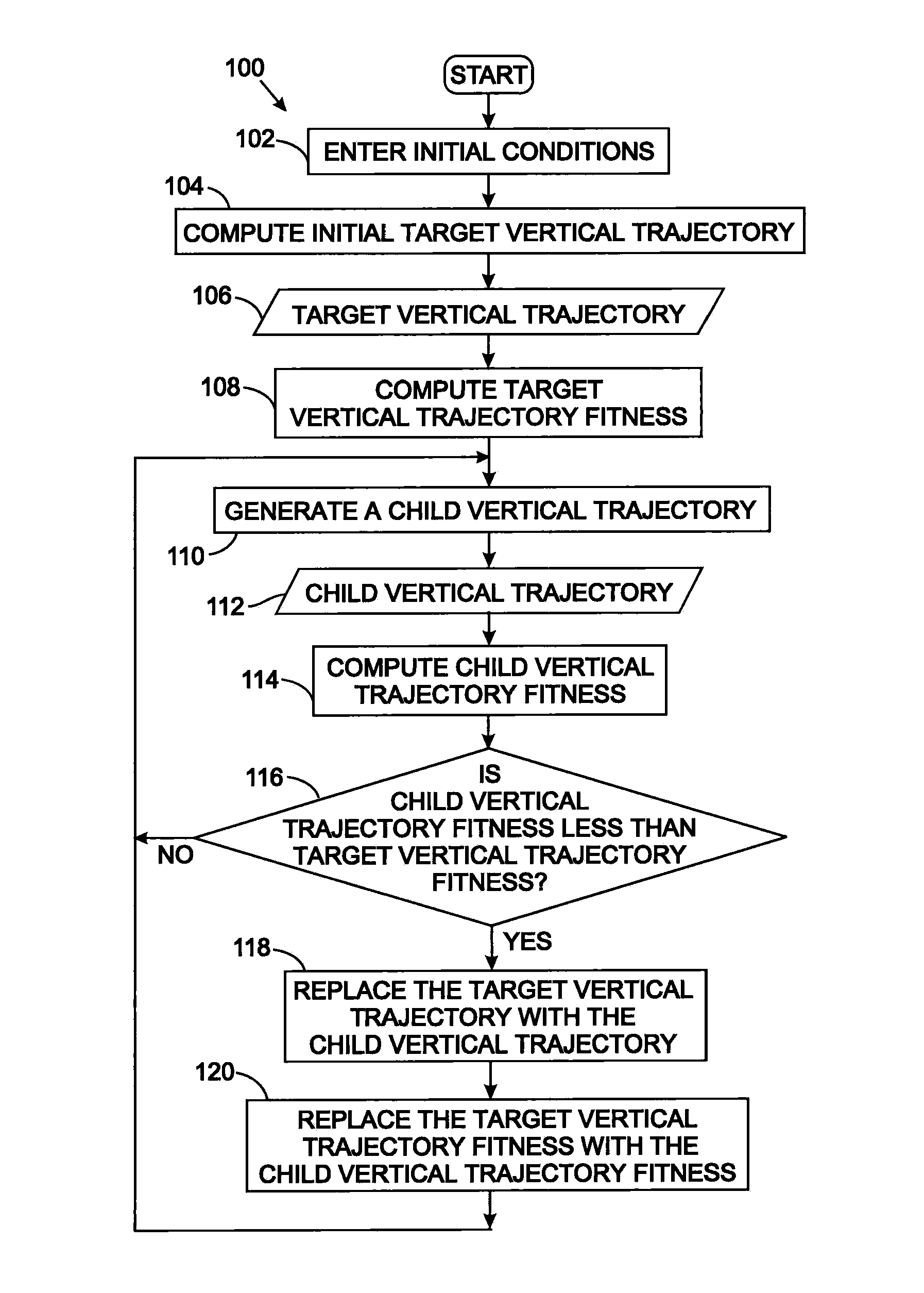
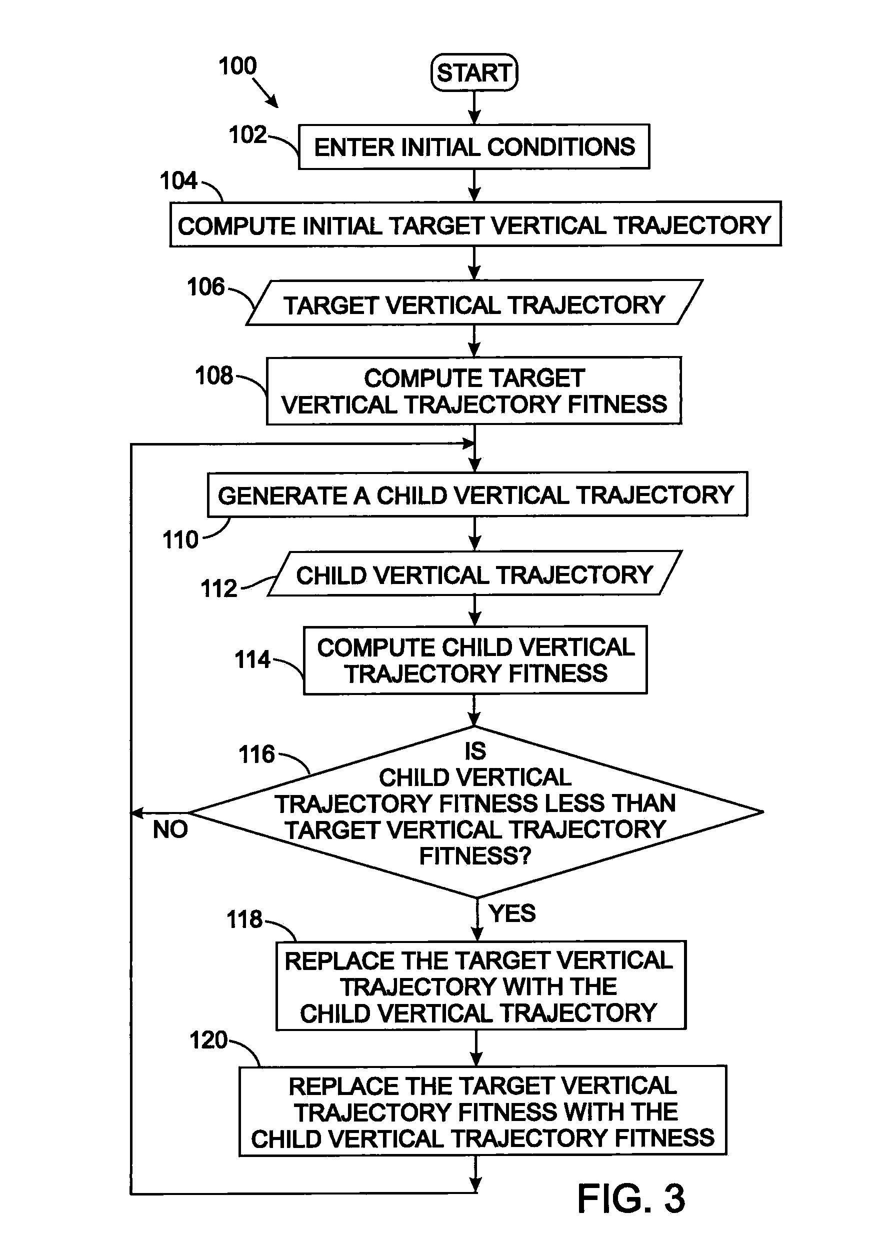
[0015]An initial target vertical trajectory is produced using aircraft performance characteristics taking into account only the altitude constraints. This method defines a series of points at distances along the flight route and a separate set of values for a plurality of aircraft parameters are determined at each of those points. The target vertical trajectory creation process ignores any speed and time constraints, thereby simplifying the derivation algorithm.
[0018]The algorithm repeats the child trajectory creation and evaluation process indefinitely. As a result, the target vertical trajectory evolves toward the optimum solution. This “genetic” target vertical trajectory derivation algorithm is far simpler than traditional methods, because less complex logic is required to solve for only one constraint and because of the use of random mutations to account for the other constraints and optimize the fuel and time costs.

Problems solved by technology

The conventional methods for determining a target trajectory are further complicated due to the fundamental flight constraints of altitude, speed, and time being interdependent and based upon the performance capabilities of the particular aircraft.
As a result, adjusting a flight trajectory to meet one constraint may cause a different constraint to be violated.
When the entire flight performance envelope of an aircraft is considered, the resulting algorithm becomes massive, complex, and fragile.
There is also the possibility of rare conditions or constraint combinations not being handled or being handled poorly.

Method used


Image

  • Aircraft vertical trajectory optimization method
  • Aircraft vertical trajectory optimization method
  • Aircraft vertical trajectory optimization method

Examples


Embodiment Construction

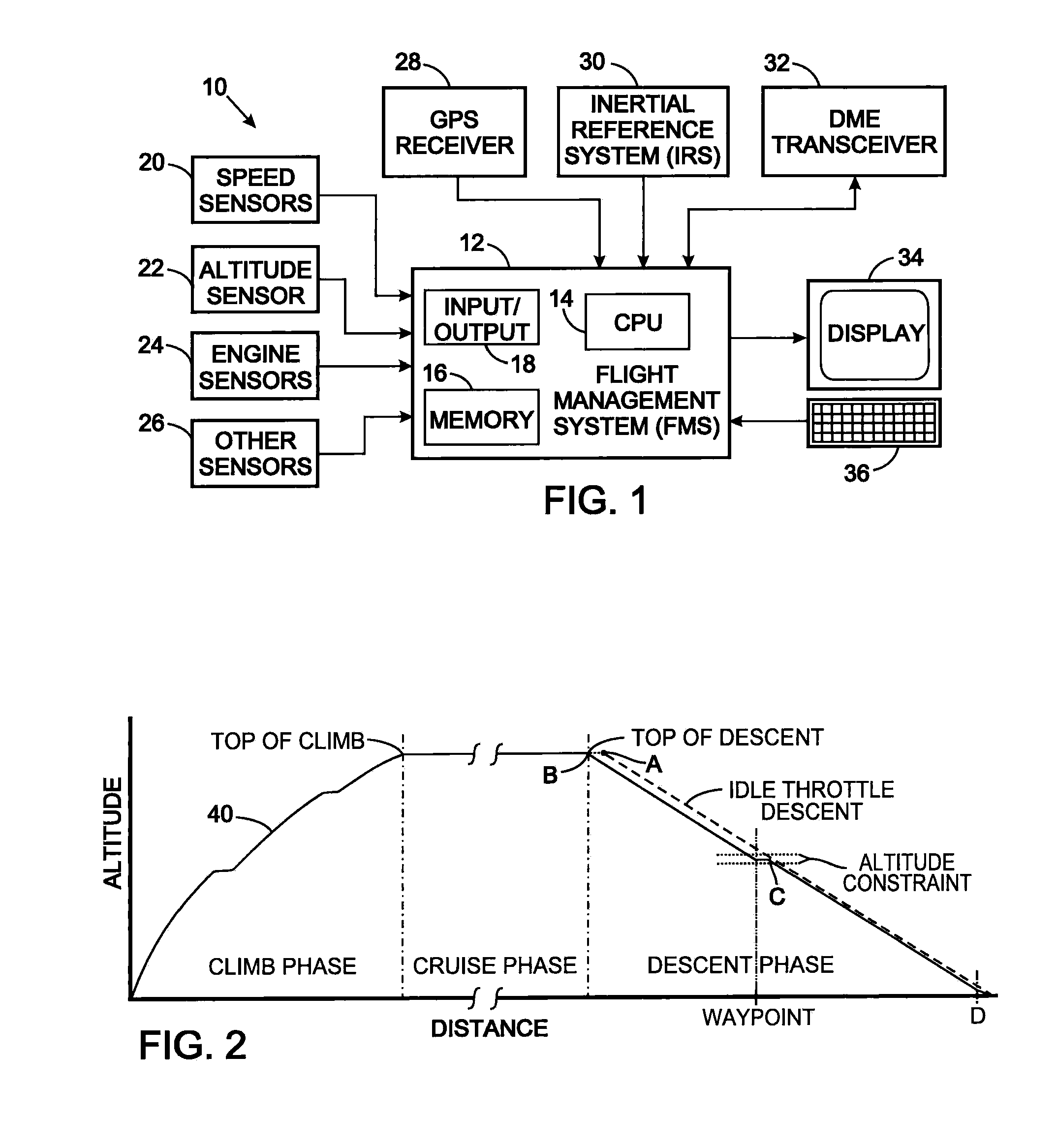
[0025]With initial reference to FIG. 1, the avionics 10 onboard an aircraft includes a flight management system (FMS) 12 that comprises a central processing unit (CPU) 14. The CPU 14 executes software that implements the flight management of the aircraft with which the FMS is used and that software includes a routine for deriving the vertical trajectory according to the present method. The software instructions for governing the operation of the FMS 12, data specifying performance characteristics of the aircraft, and other control data received and produced by the FMS are stored in a memory 16. The memory 16 comprises one or more of a random access memory, a CD-ROM, a hard disk, and other types of storage devices known in the art.

[0026]Input / output (I / O) circuits 18 interface the CPU 14 with several groups of sensors on the aircraft. The sensors, including speed sensors 20 for both the true airspeed and the vertical airspeed of the aircraft and an altitude sensor 22 are connected to...


PUM


Abstract

An target vertical trajectory for a flight plan is produced using aircraft performance characteristics taking into account only the altitude constraints, but ignoring any speed and time constraints. The target vertical trajectory is evaluated for violations of altitude, speed, and time constraints and on the basis of other criteria. An alternative vertical trajectory is generated by randomly changing parts of the target vertical trajectory, and this alternative is likewise evaluated. If the child vertical trajectory has a more robust evaluation, it becomes to new target vertical trajectory; otherwise the previous target vertical trajectory remains in place. The alternative vertical trajectory generation process is performed repeatedly and over time the target vertical trajectory evolves toward an optimum trajectory solution.

Description

CROSS-REFERENCE TO RELATED APPLICATIONS[0001]Not ApplicableSTATEMENT REGARDING FEDERALLY SPONSORED RESEARCH OR DEVELOPMENT[0002]Not ApplicableBACKGROUND OF THE INVENTION[0003]1. Field of the Invention[0004]The present invention relates to a flight management system for an aircraft, and more particularly determining a target vertical trajectory for a given flight plan of the aircraft.[0005]2. Description of the Related Art[0006]A flight management system (FMS) is a fundamental component of the avionics on an aircraft. The FMS is a dedicated computer system that automates a wide variety of in-flight tasks, a primary one of which is in-flight management of the aircraft flight plan.[0007]A navigation database, stored in the FMS, contains data for constructing the flight plan. That data include airways, waypoints, radio navigation aids (such as distance measuring equipment (DME), VHF omnidirectional range (VOR), and instrument landing systems), airports runways, runway approaches, and ai...

Claims


Application Information

Patent Timeline
Patent Type & Authority Applications(United States)
IPC IPC(8): G05D1/06
CPCG05D1/0005G05D1/0607
Inventor YOCHUM, THOMAS EDWARD
Owner UNIVERSAL AVIONICS SYST
Learn More