Method and device for determining a magnetic resonance system activation sequence
- Summary
- Abstract
- Description
- Claims
- Application Information
AI Technical Summary
Benefits of technology
Problems solved by technology
Method used
Image
Examples
Example
DETAILED DESCRIPTION OF THE DRAWINGS
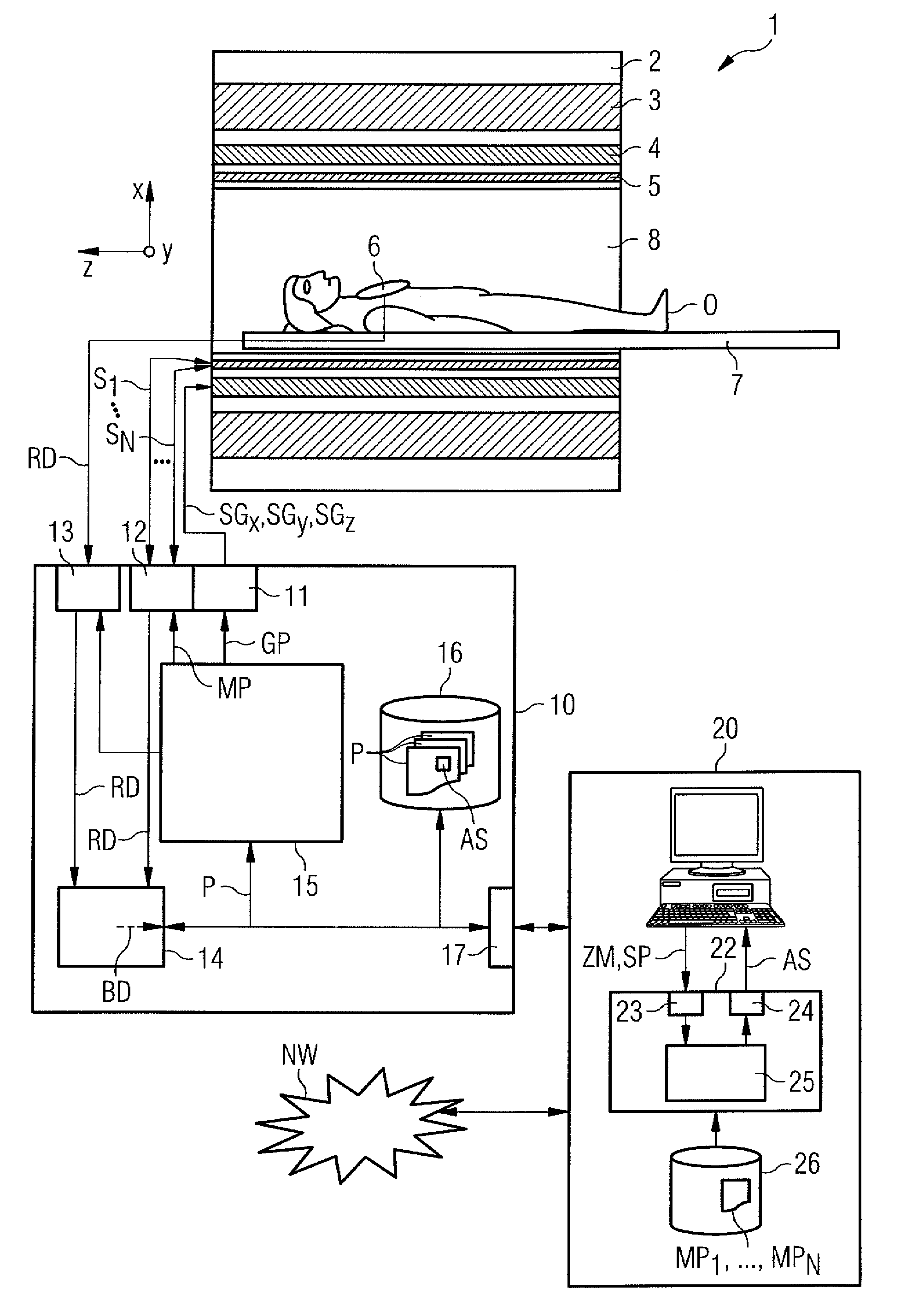
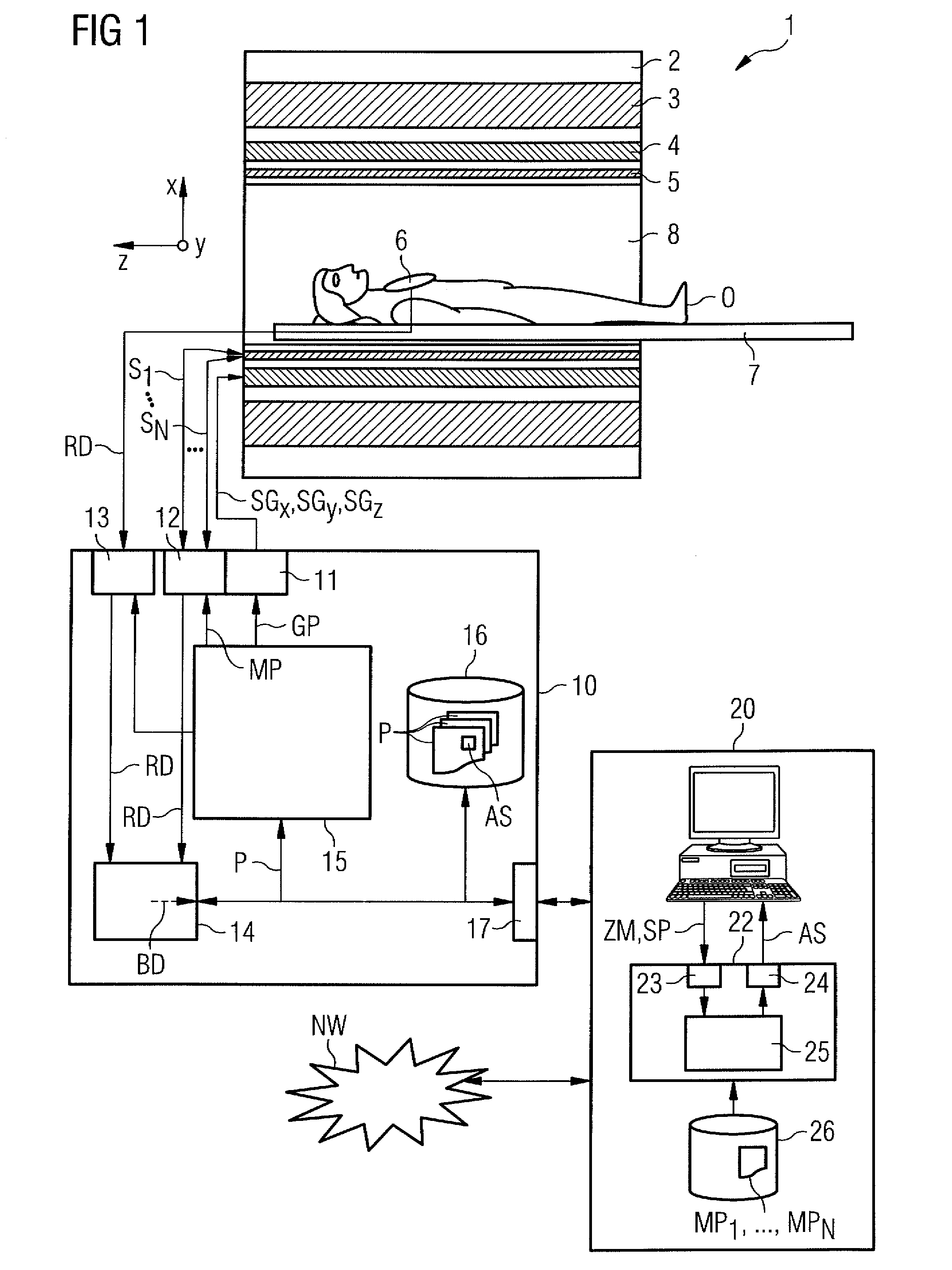
[0043]FIG. 1 shows a schematic diagram of one embodiment of a magnetic resonance unit 1. The magnetic resonance unit 1 includes an actual magnetic resonance scanner 2, with an examination chamber 8 or patient tunnel 8 located therein. A couch 7 (e.g., a table or a bed) may be moved into the patient tunnel 8, so that a patient O or subject lying thereon may be supported in a certain position within the magnetic resonance scanner 2 relative to a magnet system and a high-frequency system disposed therein during an examination, or may be moved between different positions during a measurement.
[0044]Components of the magnetic resonance scanner 2 include a basic field magnet 3, a gradient system 4 having magnetic field gradient coils to apply any magnetic field gradients in the x, y and z directions, and a whole body high-frequency coil 5. Magnetic resonance signals induced in the examination object O may be received by way of a whole body coil 5 that ma...
PUM
 Abstract
Description
Claims
Application Information
 - R&D
- Intellectual Property
- Life Sciences
- Materials
- Tech Scout
- Unparalleled Data Quality
- Higher Quality Content
- 60% Fewer Hallucinations
Browse by: Latest US Patents, China's latest patents, Technical Efficacy Thesaurus, Application Domain, Technology Topic, Popular Technical Reports.
© 2025 PatSnap. All rights reserved.Legal|Privacy policy|Modern Slavery Act Transparency Statement|Sitemap|About US| Contact US: help@patsnap.com


