
Loudspeaker magnet assembly

a technology of loudspeaker and magnet assembly, which is applied in the direction of diaphragm extension, transducer diaphragm, magnetic body, etc., can solve the problems of volume displacement, limited performance, and inability to achieve acceptable low frequency response, and achieve the effect of low profile construction

Active Publication Date: 2012-10-25
HARMAN INT IND INC
View PDF9 Cites 15 Cited by
  • Summary
  • Abstract
  • Description
  • Claims
  • Application Information

AI Technical Summary

Benefits of technology

[0015]A loudspeaker magnet assembly for a loudspeaker transducer having a voice coil is provided that has a low profile construction in accordance with the invention. The loudspeaker magnet assembly m...

Problems solved by technology

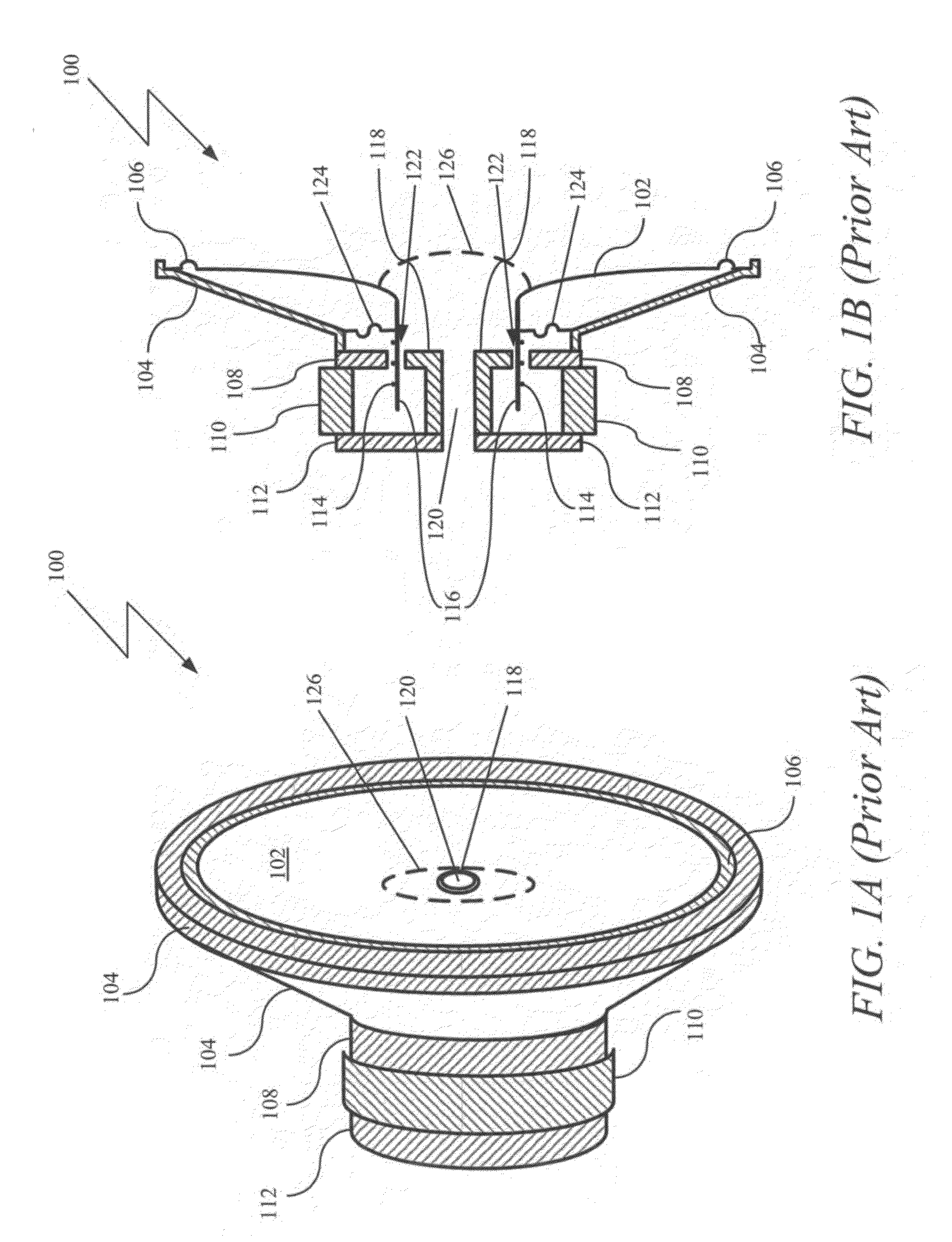
One common problem with smaller sized loudspeakers is as the size of the loudspeakers becomes smaller, achieving acceptable low frequency response becomes more difficult.
Since smaller loudspeakers have a smaller diaphragm and stiffer suspension, the volume displacement, and thus the performance, is limited by the ability to manufacture loudspeakers with very low stiffness and high excursion capabilities.
A general problem with the current construction of edge-driven speakers is the difficulty of precisely aligning the components during manufacturing, as the magnetic air gap is shielded by the diaphragm.
This forces the removal of all alignment gauges prior to the placement of the diaphragm / coil assembly, and thus causes uncertainty in location of the voice coil relative to the motor.
An additional general problem with the current construction of loudspeakers is that spurious vibration of portions of the surround suspension members occur at high audio frequencies.
These spurious vibrations may be transmitted to the diaphragm through the suspension, thereby degrading the high frequency performance of the speakers.
Also, with the current loudspeaker construction, the maximum amplitude of vibration is limited in smaller sized loudspeakers, preventing low frequency responses from the smaller diameter speakers.
Furthermore, the frame construction of even smaller sized loudspeakers prevents these loudspeakers from being thin enough for use in laptops and to electronic tablet devices.

Method used


Image

  • Loudspeaker magnet assembly
  • Loudspeaker magnet assembly
  • Loudspeaker magnet assembly

Examples


Embodiment Construction

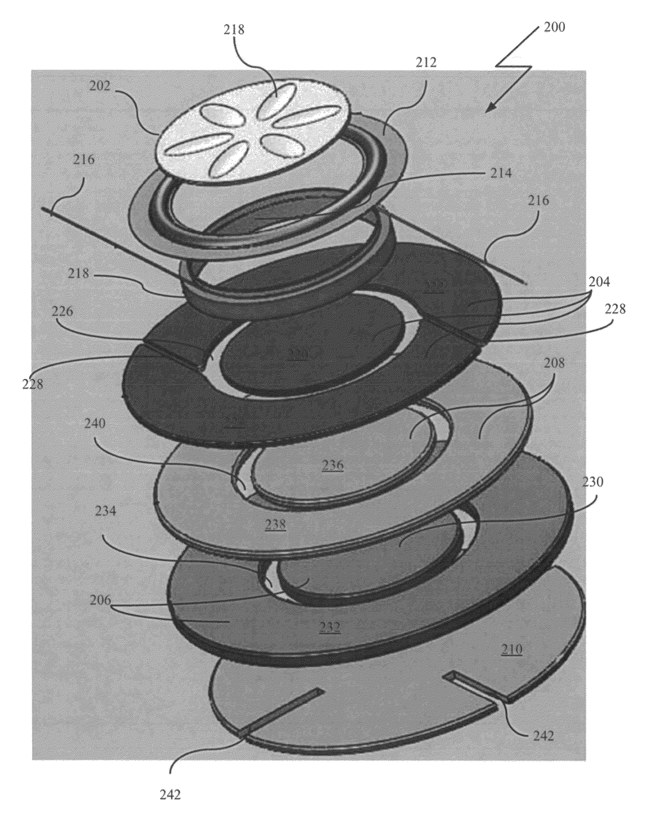
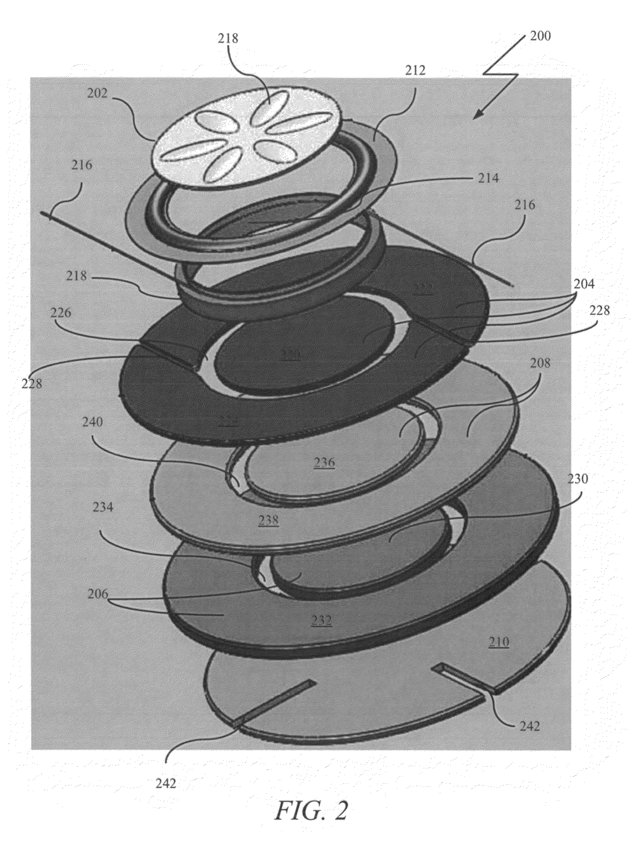
[0051]In order to solve the problems in the prior art, a loudspeaker magnet assembly for a loudspeaker transducer having a voice coil is provided that has a low profile construction in accordance with the invention. The loudspeaker magnet assembly may include: a first magnet assembly; top plate positioned below the first magnet assembly; second magnet assembly positioned below the top plate; and bottom plate positioned below the second magnet assembly.

[0052]The first magnet assembly may include an annular outer magnet and a circular inner magnet. The annular outer magnet has an outer diameter and an inner diameter, where the inner diameter defines a vacant circular center within the annular outer magnet. The circular inner magnet has a diameter less than the inner diameter of the annular outer magnet and is positioned concentrically within the vacant circular center of the annular outer magnet. The difference in length between the diameter of the circular inner magnet and the inner ...


PUM


Abstract

A loudspeaker magnet assembly for a loudspeaker transducer having a voice coil is provided that has a low profile construction. The loudspeaker magnet assembly may include: a first magnet assembly; top plate position below the first magnet assembly; second magnet assembly positioned below the top plate; and bottom plate positioned below the second magnet assembly. The first magnet assembly may include an annular outer magnet and a circular inner magnet. The top plate may include an annular outer top plate and a circular inner top plate and the second magnet assembly may include an annular outer magnet and a circular inner magnet.

Description

CROSS-REFERENCE To RELATED APPLICATIONS[0001]This application claims priority to U.S. provisional patent applications Ser. No. 61 / 474,555, filed Apr. 12, 2011, titled “LOUDSPEAKER MAGNET ASSEMBLY;” Ser. No. 61 / 474,527, filed Apr. 12, 2011, titled “CHANNEL MAGNET ASSEMBLY;” No. 61 / 474,611, filed Apr. 12, 2011, titled “LOW PROFILE LOUDSPEAKER WITH REINFORCED DIAPHRAGM;” Ser. No. 61 / 474,592, filed Apr. 12, 2011, titled “LOW PROFILE LOUDSPEAKER SUSPENSION SYSTEM,” all of which are incorporated by reference in this application in their entirety.BACKGROUND OF THE INVENTION[0002]1. Field of the Invention[0003]This invention relates to loudspeaker transducers, and in particular, the configuration of a loudspeaker magnet assembly for a low profile loudspeaker transducer.[0004]2. Related Art[0005]Sound reproduction devices such as loudspeakers are utilized in a broad range of applications in many distinct fields of technology, including both the consumer and industrial fields. Generally, loud...

Claims


Application Information

Patent Timeline
IPC IPC(8): H04R1/00
CPCH01F7/0289H04R1/06H04R9/022H04R9/025H04R2207/021H04R9/02H04R9/04
Inventor STEAD, BRENDON
Owner HARMAN INT IND INC
Learn More