Mounting arrangement for an eccentric shaft in a refrigeration compressor

a technology of eccentric shaft and refrigeration compressor, which is applied in the direction of positive displacement liquid engine, liquid fuel engine, lighting and heating apparatus, etc., can solve the problems of increasing the efficiency and durability of the compressor, reducing the number of components, and increasing the tension on the structure of the compressor, so as to reduce the vertical dimension of the compressor, reduce the number of components, and minimize the mounting steps and possible mounting misalignments

Active Publication Date: 2012-10-25
EMBRACO IND DE COMPRESSORES E SOLUCOES EM REFRIGERACAO LTDA
View PDF13 Cites 0 Cited by
  • Summary
  • Abstract
  • Description
  • Claims
  • Application Information

AI Technical Summary

Benefits of technology

[0024]In the proposed solution, the block, by being formed in a single piece, presents the already mentioned advantages related to construction, assembly and alignment of the component parts, carrying two radial bearings axially spaced from each other and around which the electric motor rotor is affixed to the eccentric shaft. Thus, the rotor of the electric motor occupies, in the assembly, a height coincident with that of the shaft hub, reducing the vertical dimension of the compressor and allowing the electromagnetic forces p

Problems solved by technology

It should be further noted that, besides the angular deformations, there can also occur manufacturing geometric deviations, which increase the misalignment of the eccentric shaft 20 in relation to the associated elements of the compression mechanism, impairing even more the efficiency and durability of the compressor.
This application of electromagnetic force generates a bending moment on the eccentric shaft 20, which results in a tension force on its structure, tending to cause deformation of said shaft.
However, this solution does not avoid the negative effects regarding the forces resulting from mounting the rotor 32 in an end portion of the eccentric shaft 20, which defines an axial extension in cantilever sufficient for mounting the rotor 32.
Other negative aspect of this prior art solution is an undesirable and even unacceptable increase in the compressor height.
This so

Method used


Image

  • Mounting arrangement for an eccentric shaft in a refrigeration compressor
  • Mounting arrangement for an eccentric shaft in a refrigeration compressor
  • Mounting arrangement for an eccentric shaft in a refrigeration compressor

Examples


Embodiment Construction

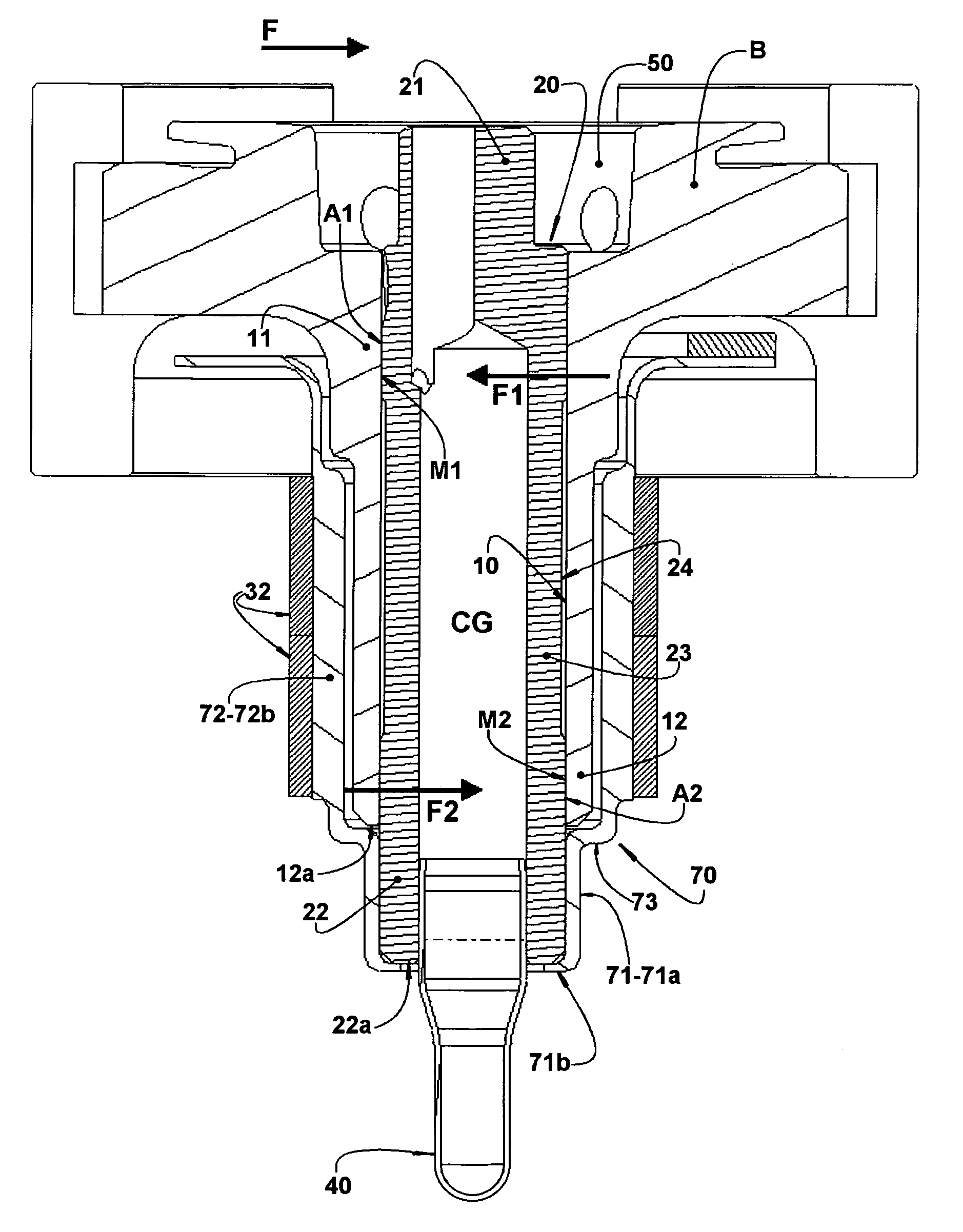
[0032]As illustrated, the present invention is applied to a refrigeration compressor, of any size (small, medium or large), either hermetic or not, of the scroll or reciprocating type and which presents, in the interior of a shell (not illustrated), a single block B which comprises, in a single piece, a shaft hub 10 having a first and a second end portion 11, 12, said shaft hub 10 housing an eccentric shaft 20 which incorporates an eccentric end portion 21 projecting outwardly from the first end portion 11 of the shaft hub 10.

[0033]The second end portion 12 of the shaft hub 10 presents an annular end face 12a which, in some compressor constructions (FIGS. 4 and 5), is coplanar to an end face 22a of the free end portion 22 of the eccentric shaft 20.

[0034]As illustrated in FIG. 3, the free end portion 22 of the eccentric shaft 20 projects beyond the annular end face 12a of the second end portion 12 of the shaft hub 10, whilst as illustrated in the constructive variants of FIGS. 4 and ...


PUM


Abstract

The compressor of the invention includes a block (B) defining a shaft hub having a first and a second end portion and housing an eccentric shaft having a median portion radially journalled in the shaft hub, and a free end portion carrying the rotor of an electric motor. The first and the second end portions of the shaft hub define radial bearings for the shaft and a support member is formed by a coupling portion, affixed to the free end portion of the shaft, and by a mounting portion, projecting axially and radially from the coupling portion, externally to the shaft hub and around the median portion of the shaft. The rotor is affixed to the mounting portion, concentrically to the eccentric shaft and surrounding the shaft hub.

Description

FIELD OF THE INVENTION[0001]The present invention refers to a constructive arrangement to provide a more effective bearing of an eccentric shaft in the block which carries the compression mechanisms of a refrigeration compressor, whether small, medium or large, either hermetic or not.PRIOR ART[0002]In some prior art constructive solutions, as illustrated in FIGS. 1 and 2, the mechanical assembly of the refrigeration compressor is basically formed by a block B comprising a shaft hub 10, in the interior of which is radially journalled an eccentric shaft 20, which is rotatively driven by an electric motor of the compressor, for impelling a compression mechanism.[0003]In the prior art compressor construction, the motor 30 generally comprises a stator 31 attached to the block B, and a rotor 32 formed by a core around which are mounted permanent magnets, said rotor being mounted to a free end portion 22 of the eccentric shaft 20 which projects axially outwardly from the shaft hub 10.[0004...

Claims


Application Information

Patent Timeline
IPC IPC(8): F04C23/02F04C18/00
CPCF01C21/02F04B27/0404F04B39/0094F04C18/0207F04C29/0042F25B1/02F04C29/0078F04C2230/604F04C2240/601F04C2240/80F04C29/0057
Inventor COUTO, PAULO ROGERIO CARRARAVOLLRATH, INGWALD
Owner EMBRACO IND DE COMPRESSORES E SOLUCOES EM REFRIGERACAO LTDA
Why Eureka
Try Eureka