Load balancing in femtocells

a femtocell and load balancing technology, applied in the field of communication, can solve the problems of not defining an x2 interface for femtocell base stations in the 3gpp lte standard specification, and the load balancing policy of typical femtocell base stations is not necessarily efficient, so as to reduce transmission power, shrink the expansion cell coverage, and reduce transmission power

Active Publication Date: 2012-10-25
KT CORP
View PDF9 Cites 54 Cited by
  • Summary
  • Abstract
  • Description
  • Claims
  • Application Information

AI Technical Summary

Benefits of technology

[0012]In accordance with an embodiment of the present invention, a method may be provided for load balancing in femtocells at a femtocell base station. The method may include determining whether a cell load status of the femtocell base station exceeds a certain load level, and initiating handover of at least one user equipment coupled to the femtocell base station to a target base station by shrinking cell coverage of the femtocell base station when the cell load status of the femtocell base station exceeds the certain load level.
[0028]In accordance with another embodiment of the present invention, a femtocell base station may include a monitor unit, a cell coverage control unit, an access control unit. The monitor unit may be configured to determine whether a cell load status of the femtocell base station reaches a certain load level. The cell coverage control unit may be configured to shrink cell coverage of the femtocell base station when the cell load status reaches the certain load level by reducing transmission power of the femtocell base station. The access control unit may be configured to provide handover to at least one user equipment coupled to the femtocell base station to a target base station through an X2 interface when the cell coverage is shrunk by the cell coverage control unit.

Problems solved by technology

However, the 3GPP LTE standard specification does not define an X2 interface for femtocell base stations such as, for example, HeNBs or HNBs
Particularly, for load balancing, a typical femtocell base station simply denies access of user equipment when the typical femtocell base station has a load exceeding a certain threshold.
Such a load balancing policy for the typical femtocell base station is not necessarily efficient because neighbor femtocell base stations may have available resources to accept additional user equipment.

Method used


Image

  • Load balancing in femtocells
  • Load balancing in femtocells
  • Load balancing in femtocells

Examples


Embodiment Construction

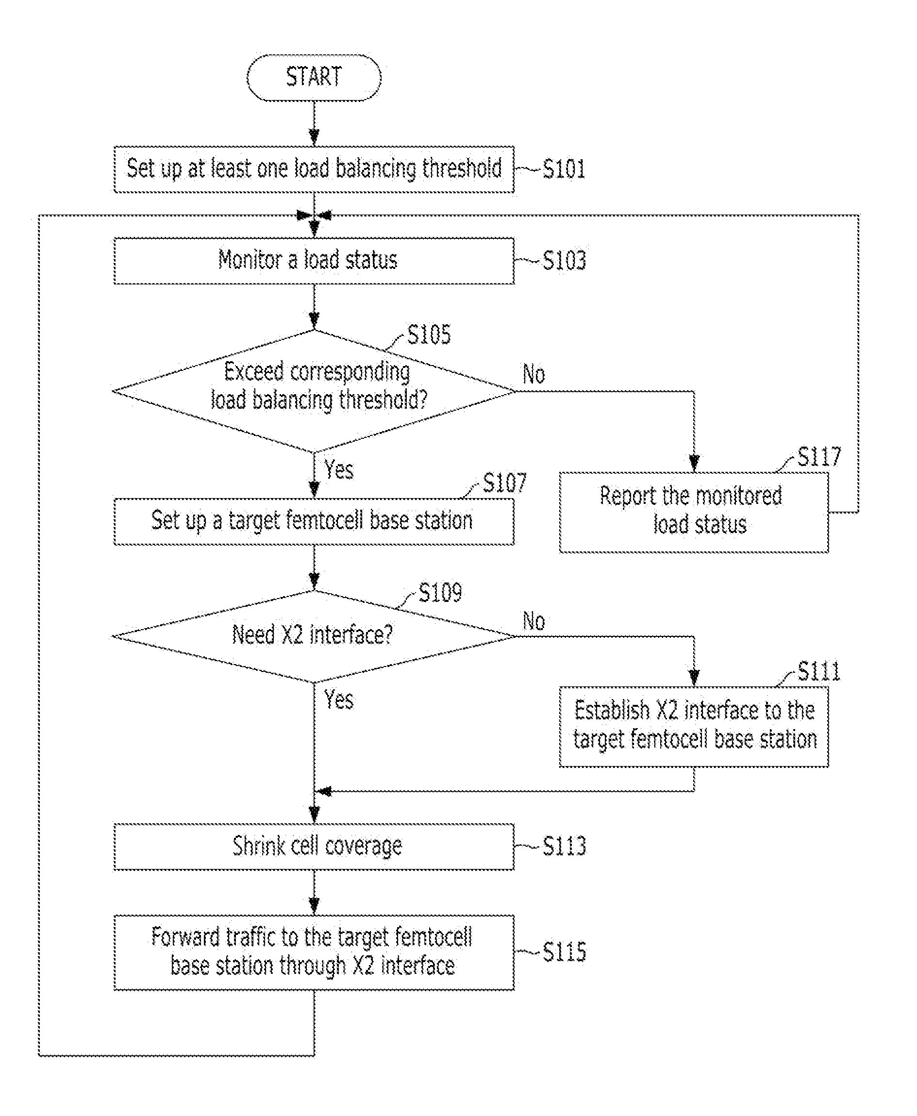
[0041]Reference will now be made in detail to embodiments of the present invention, examples of which are illustrated in the accompanying drawings, wherein like reference numerals refer to like elements throughout. The embodiments are described below, in order to explain the present invention by referring to the figures.

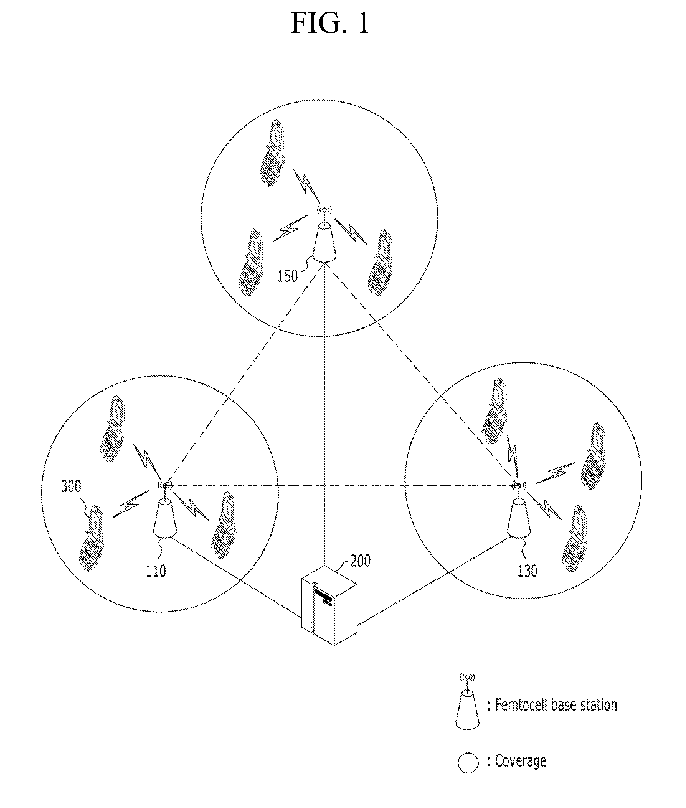
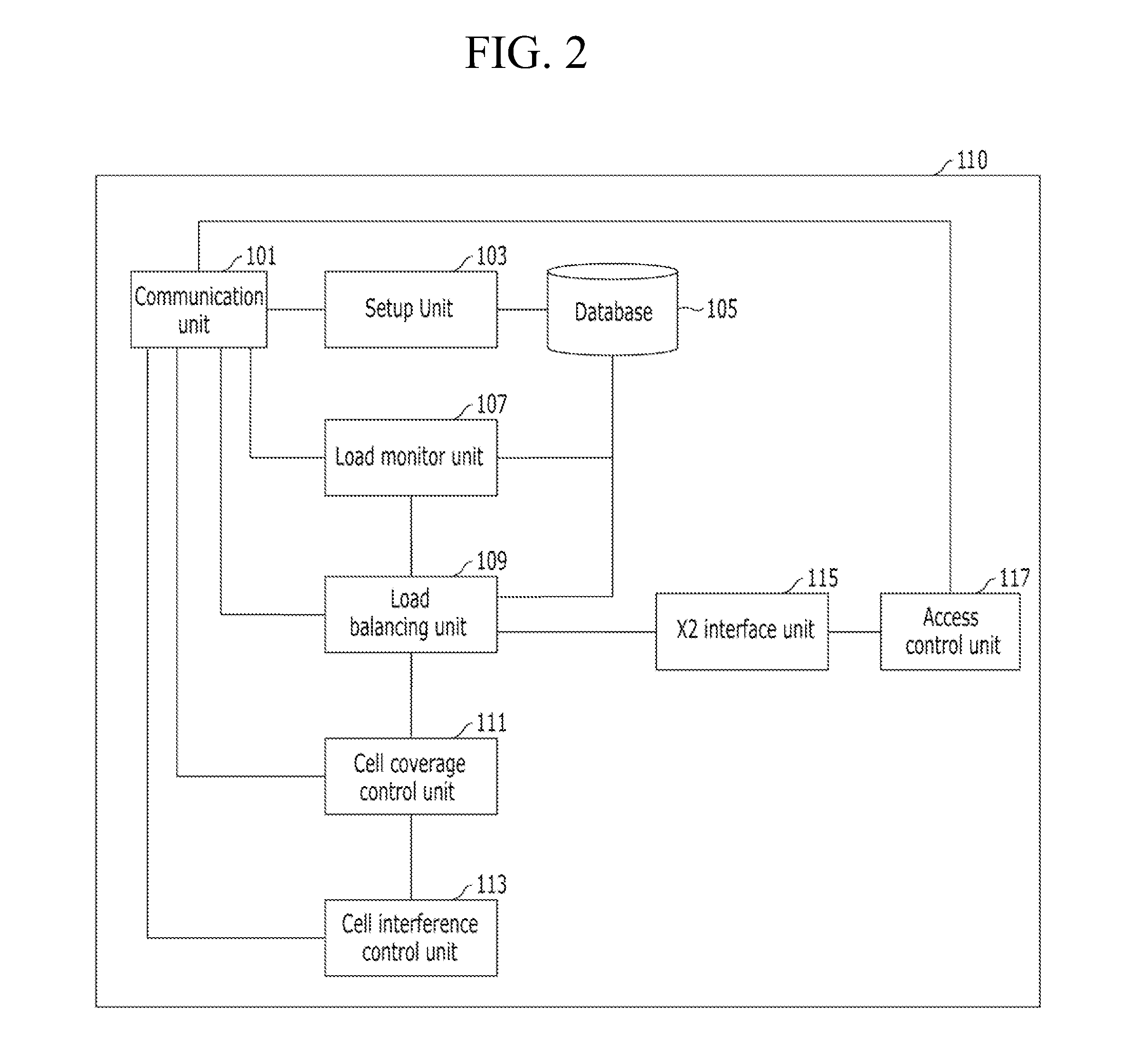
[0042]Embodiments of the present invention will be described as being applied to a long term evolution (LTE) network. The present invention, however, is not limited thereto. Embodiments of the present invention might be similarly applied to other communication networks such as, for example, global system for mobile communication (GSM), code division multiple access 2000 (CDMA-2000), time division synchronous code division multiple access (TD-SCDMA), worldwide interoperability for microwave access (WiMAX), and wireless broadband (WiBro). Hereinafter, load balancing in femtocells using an X2 interface in accordance with an embodiment of the present invention will be de...


PUM


Abstract

A method may be provided for load balancing in femtocells. Determination may be made as to whether a cell load status of the femtocell base station exceeds a certain load level. When the cell load status of the femtocell base station reaches and / or exceeds the certain load level, handover of at least one user equipment coupled to the femtocell base station to a target base station may be initiated by shrinking cell coverage of the femtocell base station.

Description

CROSS REFERENCE TO PRIOR APPLICATIONS[0001]The present application claims priority under 35 U.S.C. §119 to Korean Patent Application No. 10-2011-0038037 (filed on Apr. 22, 2011), which is hereby incorporated by reference in its entirety.FIELD OF THE INVENTION[0002]The present invention relates to communications and, in particular, to base station load balancing in femtocells.BACKGROUND OF THE INVENTION[0003]A femtocell base station is designed to connect user equipment located in a femtocell to a service provider's network. A femtocell may denote a small service area covered by a femtocell base station. For example, the femtocell may be a home or a small business office in a cellular system. The range of a femtocell base station may be about 10 meters. The femtocell base station has been applied to a Long Term Evolution (LTE) communication network. The 3rd Generation Partnership Project (3GPP) has introduced standard-specifications for LTE technology. In 3GPP LTE standard specificat...

Claims


Application Information

Patent Timeline
Patent Type & Authority Applications(United States)
IPC IPC(8): H04W36/22H04W36/08H04W24/00H04W36/16
CPCH04W36/22Y02B60/50H04W84/045Y02D30/70H04W92/20H04W16/08
Inventor HA, KWANG-JUN
Owner KT CORP
Why Eureka
Try Eureka