
Controller For Automatic Control And Optimization Of Duty Cycled HVAC&R Equipment, And Systems And Methods Using Same

a technology of automatic control and optimization, applied in the field of electronic controllers, can solve the problems of difficult retrofitting existing installations with these methodologies, inability to take advantage of these energy related improvements, and inability to add a conventional energy saving methodology to an existing hvac&r system,

Inactive Publication Date: 2012-11-01
PACECONTROLS
View PDF7 Cites 61 Cited by
  • Summary
  • Abstract
  • Description
  • Claims
  • Application Information

AI Technical Summary

Benefits of technology

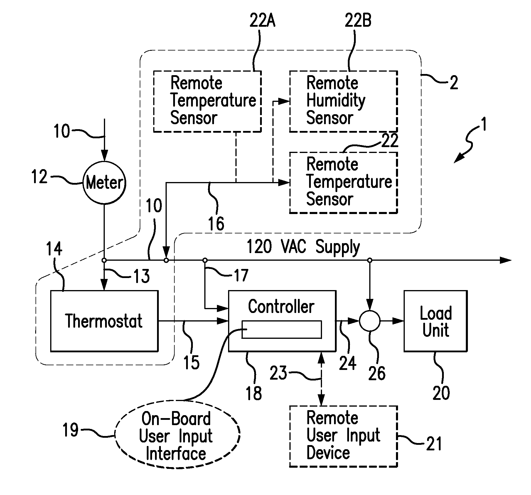
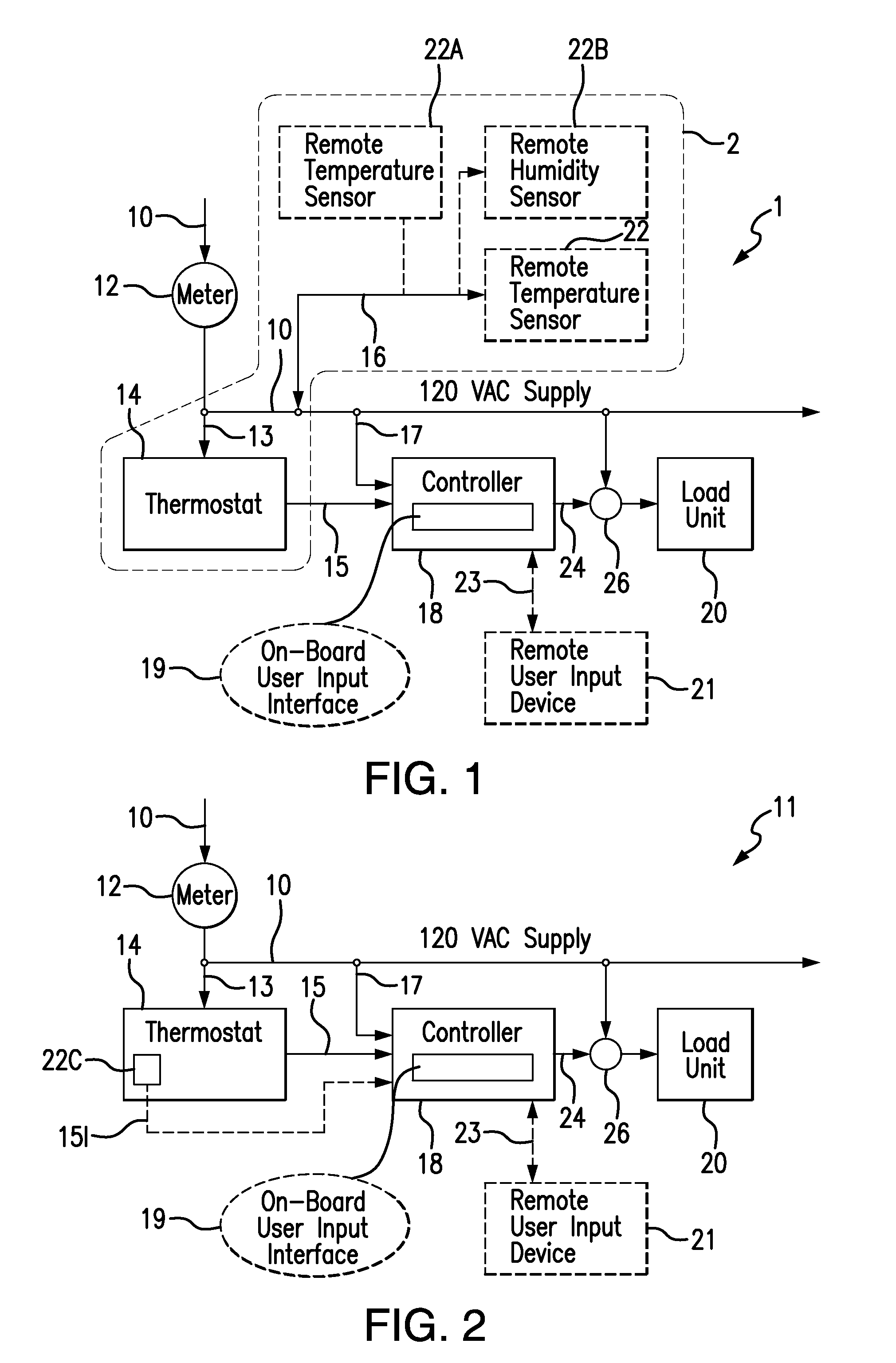
[0007]A feature of the present invention is to provide an electronic controller device for a heating, ventilating, air conditioning and / or refrigeration (HVAC&R) system that is controlled using optimized duty cycling, which can automate the configuration and control of optimal “on” and “off” cycle time durations for a load device or devices in the HVAC&R system.
[0008]Another feature of the present invention is to retrofit a HVAC&R system that is controlled using optimized duty cycling with an electronic controller device, which can automatically configure and control execution of optimal “on” and “off” cycle time durations for a load device or devices in the HVAC&R system.

Problems solved by technology

Although these improvements can be found on most new HVAC&R equipment, there is a large installed base of older existing equipment still in operation but often unable to take advantage of these energy related improvements as retrofit improvements.
It is often difficult to retrofit existing installations with these methodologies because the methodologies are highly dependent on the HVAC&R equipment, configuration, and installation details.
Adding a conventional energy saving methodology to an existing HVAC&R system can be costly and time consuming.

Method used


Image

  • Controller For Automatic Control And Optimization Of Duty Cycled HVAC&R Equipment, And Systems And Methods Using Same
  • Controller For Automatic Control And Optimization Of Duty Cycled HVAC&R Equipment, And Systems And Methods Using Same
  • Controller For Automatic Control And Optimization Of Duty Cycled HVAC&R Equipment, And Systems And Methods Using Same

Examples


example 1

[0115]This example illustrates the temperature behavior of the conditioned space while operating the algorithm in the minimum energy mode for a cooling application. In the three plots shown in FIGS. 15, 16, and 17, FIG. 15 shows the behavior of the OEM control (“OEM Control Command”) and its corresponding conditioned space temperature (above). The conditioned space temperature varies between high and low deadband values (68° F. and 66° F.). The OEM temperature setpoint value is halfway between the deadbands and denoted as T*. The control objective of the OEM thermostat is to maintain the conditioned space temperature at T* with variations not to exceed the high and low deadband values.

[0116]The plots of FIGS. 16 and 17 show two DRC control signals and their associated conditioned space temperatures for two different settings of the weight parameters. In the plot of FIG. 16, the parameters of the indicated formula for calculating the performance index (“J”) are set to Q=10, R=1, and ...

example 2

[0118]This example illustrates the temperature behavior of the conditioned space while operating the algorithm in the power limit mode for a cooling application. In the two plots of FIGS. 18 and 19, the plot of FIG. 18 shows the behavior of the OEM control (“OEM Control Command”) and its corresponding conditioned space temperature (above). The conditioned space temperature varies between high and low deadband values (T-hi and T-lo). The OEM temperature setpoint value is halfway between the deadbands and denoted as T*. The control objective of the OEM thermostat is to limit or minimize the runtime during time intervals of t1 time units or less (this is illustrative and chosen as the “on” time of the OEM controller). This time value may correspond to the time window used for calculation of the electrical demand charge (15 or 30 minutes typically). A second objective is for the DRC algorithm to maintain the same temperature setpoint as the OEM controller.

[0119]In the plot of FIG. 19, t...


PUM


Abstract

An electronic controller device for automatic control of a heating, ventilating, air conditioning or refrigeration (HVAC&R) system has a digital recycle counter that is capable of intercepting a thermostat command for cooling, refrigeration, or heating and replacing the thermostat command with a modulated binary signal that operates in an “on” state or “off” state, and a computer-readable storage medium that comprises a program that includes an auto-configuration mode that is capable of determining a base line performance of the HVAC&R system through a commissioning phase and is capable of determining an adjusted performance based on energy consumption, temperature regulation, humidity regulation, or power limit or any combination thereof. The program can adjust the digital recycle counter “on” and “off” states based on the adjusted performance determination to reduce energy consumption.

Description

[0001]This application is a continuation of International Patent Application No. PCT / US2010 / 056948, filed Nov. 17, 2010, which claims the benefit of prior U.S. Provisional Patent Application No. 61 / 262,281, filed Nov. 18, 2009, and U.S. patent application Ser. No. 12 / 794,116, filed Jun. 4, 2010, which are incorporated in their entirety by reference herein.BACKGROUND OF THE INVENTION[0002]The present invention relates to an electronic controller for automatically controlling and optimizing duty cycled, electrical energy-consuming equipment, including gas-, oil-, and propane-fired heating equipment controlled via electrically powered control systems. The present invention also relates to heating, ventilating, air conditioning, and refrigeration equipment systems incorporating the electronic controller and methods of using the controller in such systems.[0003]Heating, ventilating, air conditioning and / or refrigeration (“HVACR” or “HVAC&R”) control systems have been designed to perform ...

Claims


Application Information

Patent Timeline
Patent Type & Authority Applications(United States)
IPC IPC(8): B64D13/00
CPCF24F11/006F24F2011/0071F24F2011/0047F24F2011/0075G05D23/1905F24F2011/0073F24F11/30F24F2140/60F24F11/62F24F11/58F24F11/61F24F11/46F24F11/64
Inventor KOLK, RICHARD A.MILLS, JR., THOMAS A.BUDNEY, STANLEY M.
Owner PACECONTROLS
Learn More