Doorstop Bar

a technology for preventing doors and windows, applied in the field of doors and windows, can solve the problems of occupying too much space, affecting the storage of doors, and being prone to kicks and falls, and achieve the effect of better storag

Inactive Publication Date: 2012-11-08
CHINGS SHEN ENTERPRISE CORP
View PDF5 Cites 13 Cited by
  • Summary
  • Abstract
  • Description
  • Claims
  • Application Information

AI Technical Summary

Benefits of technology

[0007]An objective of the invention is to provide a doorstop bar, which has a hook or a loop on the stopping element at the top end thereof To store the doorstop bar, one simply hangs it on the doorknob by the hook or loop. The doorstop bar thus hangs vertically in the air and close to the door, achieving the goal of better storage.
[0008]Another objective of the invention is to provide a doorstop bar, which has a sucking element on the urging element at the bottom end thereof The sucking element can suck onto the door made of an appropriate material. Using this mechanism, the doorstop bar vertically hanging by the door does not swing randomly and hit the person who opens the door. This achieves the goal of better storage.

Problems solved by technology

However, when somebody walks by or children play around it, the doorstop bar is likely to be kicked and fall, becoming an obstacle for walking.
It may occupy too much space and have conflict with other furniture.
So it is very inconvenient.
If other family members do not notice it and pile things thereon, it will become difficult or troublesome later on when the doorstop bar is needed.
This will result in another problem.
In addition to stopping a door from being opened, the conventional doorstop bar has never been designed to have other functions.

Method used


Image

  • Doorstop Bar
  • Doorstop Bar
  • Doorstop Bar

Examples


first embodiment

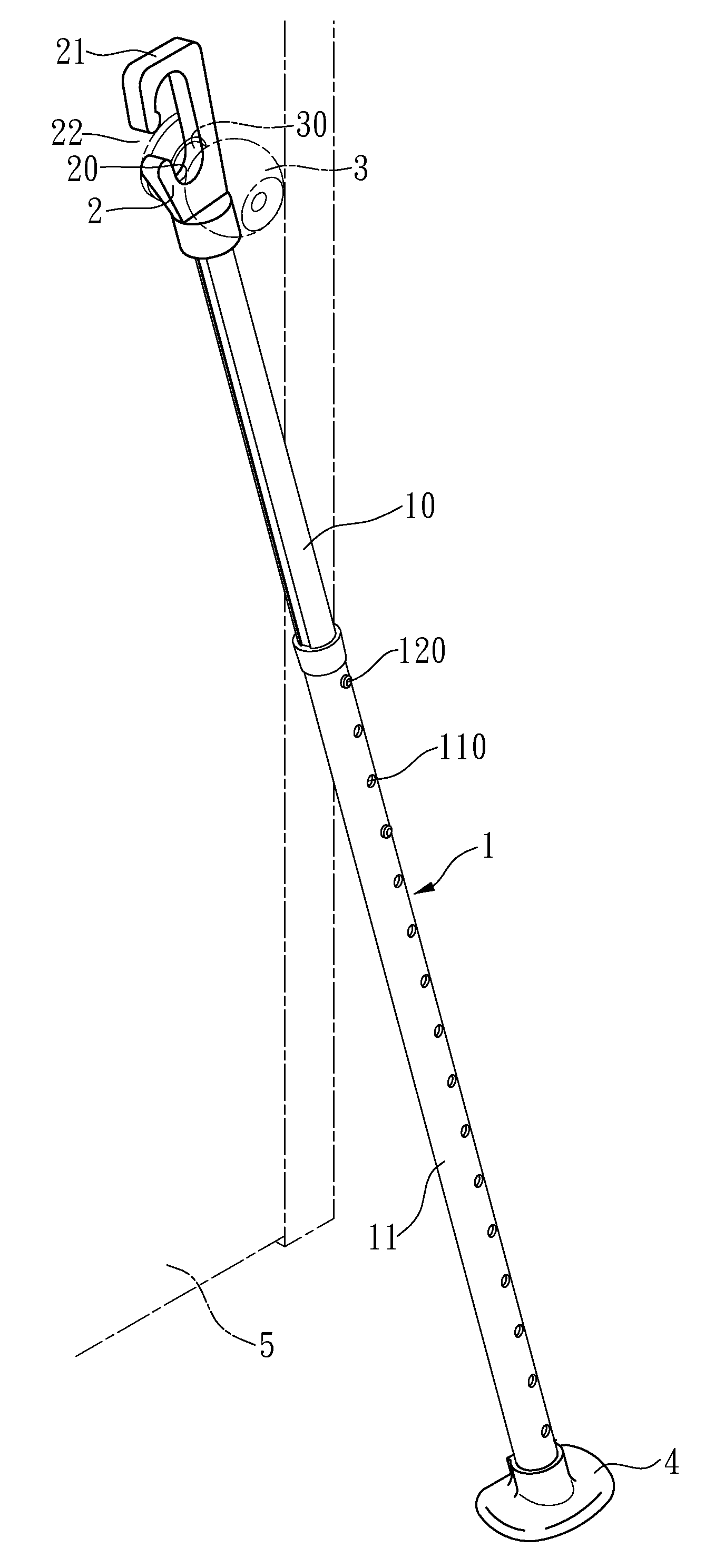
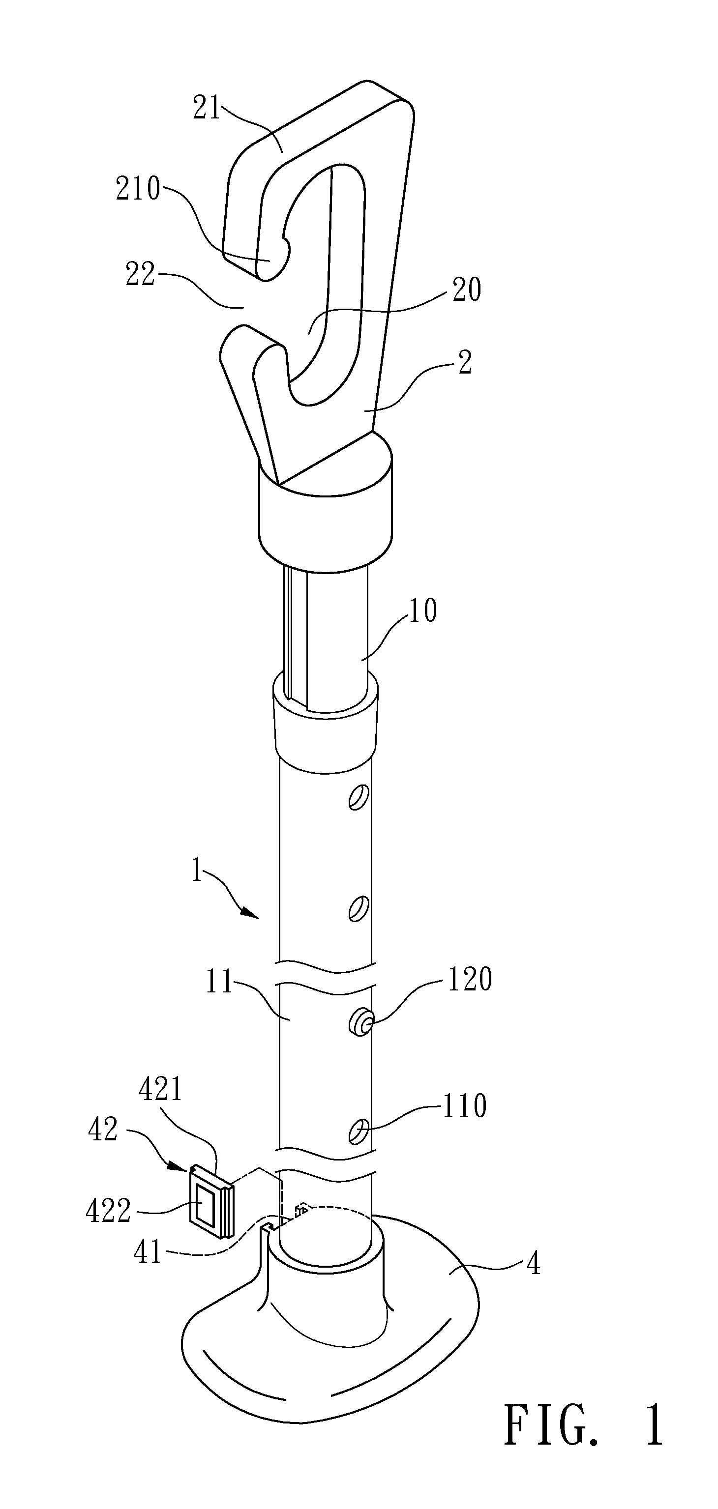
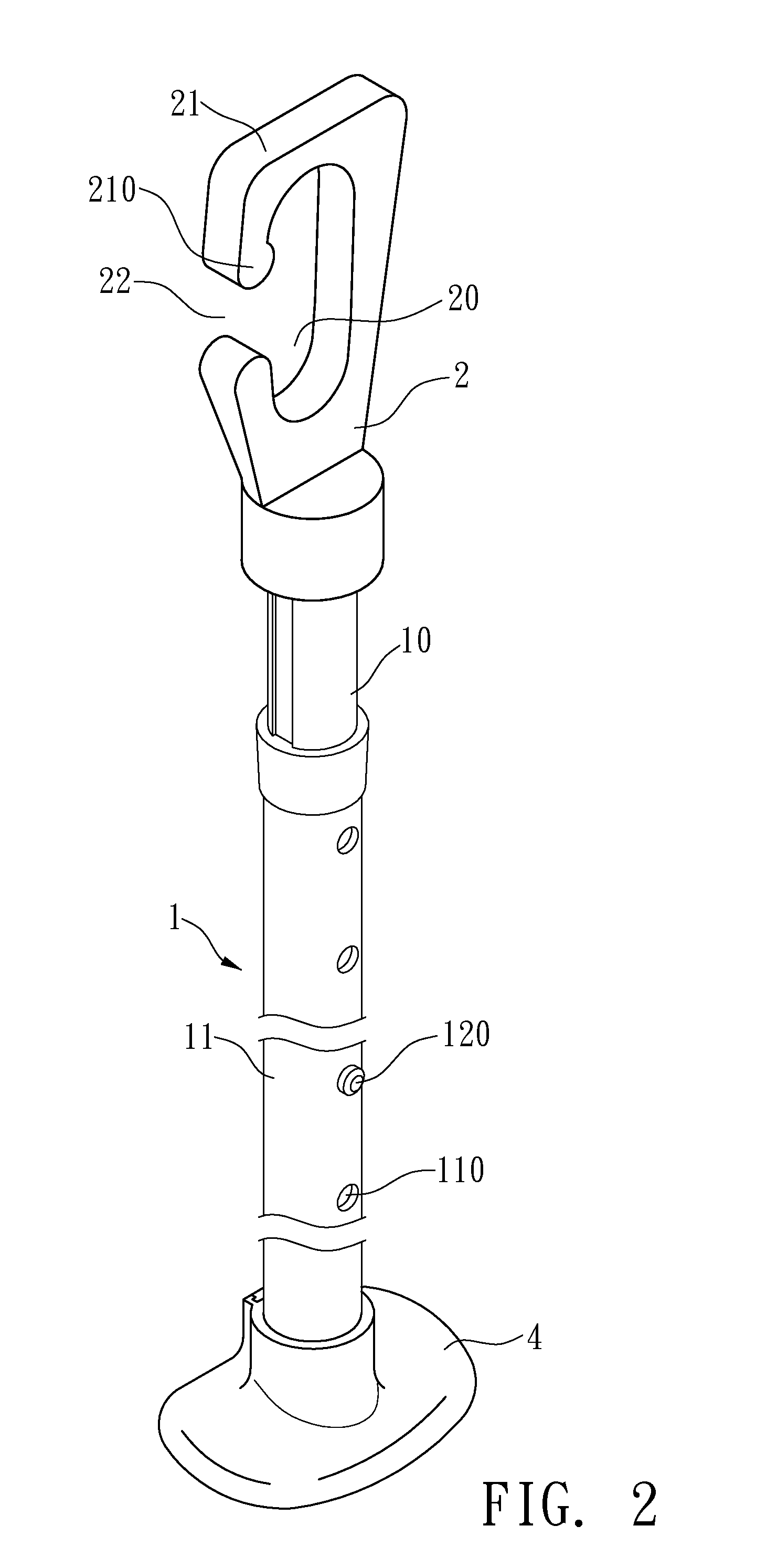
[0032]Please refer to FIGS. 1 to 2 for the invention. The disclosed doorstop bar according to the embodiment includes: a retractable bar 1, a stopping element 2, and an urging element 4.

[0033]The retractable bar 1 consists of an inner bar 10 and an outer bar 11, with the inner bar 10 inserted from one end into the outer bar 11. The inner bar 10 can extend out of or retract into the outer bar 11. A positioning element is provided between the inner bar 10 and the outer bar 11 to fix the inner bar after being retracted. As shown in FIG. 3, the positioning element in this embodiment is a bent elastic chip 12 in the inner bar 10. A protruding button 120 that can restore the position thereof after being depressed is exposed from one side of the inner bar 10. The outer bar 11 along the retracting direction of the inner bar 10 has a plurality of positioning holes 110 in a line. Each positioning hole 110 allows the protruding button 120 to go out and stop when the inner bar 10 retracts.

[0034...

second embodiment

[0039]Of course, the invention has many other embodiments that differ from the previous one in details. Please refer to FIGS. 7 and 8 for the invention. The hooking element on the stopping element 2 is implemented by a rope loop 23. The rope loop 23 can be directly mounted on the doorknob or the similar for the convenience of storage.

[0040]Besides, the sucking element 42 includes a second embedding part 423 and a sucker 424. The sucker 424 is provided on one side of the second embedding part 423. The other side of the second embedding part is embedded in the embedding recess 41.

[0041]The usage and advantages of the second embodiment are the same as the first embodiment, and are not repeated herein.

[0042]As shown in FIGS. 9 and 10, the retractable bar 5 includes an inner bar 50 inserted from one end into an outer bar 51. The inner bar 50 can extend out of or retract into the outer bar 51. A positioning element for fixing the retracted inner bar 50 is provided between the inner bar 50...


PUM


Abstract

A doorstop bar includes a retractable bar, a stopping element, and an urging element. The retractable bar is retractable to adjust the length thereof. The stopping element is provided at the top of the retractable. The stopping element has a holding part, and a hooking element so as to be hung on the doorknob of a door. The doorstop bar can function as a walking stick as well.

Description

BACKGROUND OF THE INVENTION[0001]1. Field of Invention[0002]The invention relates to a doorstop bar and, in particular, to a device that urges against a door.[0003]2. Related Art[0004]FIG. 17 shows a conventional doorstop bar. Its top end is a stopping element 81 whose opening 811 has a U, V or some other shape. When in use, the opening 811 of the stopping element 81 is aligned with and urged against the bottom of the doorknob or the similar (not shown). One further adjusts the length of the retractable bar 82 of the doorstop bar according to needs, and puts the urging element 83 at the bottom end thereof in place. This can enhance the anti-theft effect. When not in use, the retractable bar 82 is retracted for storage.[0005]Generally speaking, one usually stores the doorstop bar next to or near the door. Usually, it is stored vertically in order to save space. However, when somebody walks by or children play around it, the doorstop bar is likely to be kicked and fall, becoming an ob...

Claims


Application Information

Patent Timeline
Patent Type & Authority Applications(United States)
IPC IPC(8): E05C19/18A45B3/00
CPCA45B3/00A45B2009/007E05C19/18E05C19/004E05C17/54Y10T292/37
Inventor CHEN, PAO-LU
Owner CHINGS SHEN ENTERPRISE CORP
Why Eureka
Try Eureka