Decorative light hanging system

Inactive Publication Date: 2012-11-08
RINCK LANCE
View PDF6 Cites 17 Cited by
  • Summary
  • Abstract
  • Description
  • Claims
  • Application Information

AI Technical Summary

Benefits of technology

[0009]In another embodiment, the hanger is adapted for removing the second magnetic disks from the first magnetic disks. This embodiment enables a consistent lighted outline of the building structure to be presented between each use of the system by maintaining the first magnetic dis

Problems solved by technology

These multi-piece device bases are often bulky and unattractive when not coupled with the mounts and secured light strands causing users to remove the base between each use and defeating the purpose of using a “permanent” base.
Another problem related to hanging decorative lights on a building structure is the danger and difficulty in

Method used


Image

  • Decorative light hanging system
  • Decorative light hanging system
  • Decorative light hanging system

Examples


Embodiment Construction

[0016]As required, detailed embodiments of the present invention are disclosed herein; however, it is to be understood that the disclosed embodiments are merely exemplary of the invention, which may be embodied in various forms. Therefore, specific structural and functional details disclosed herein are not to be interpreted as limiting, but merely as a basis for the claims and as a representative basis for teaching one skilled in the art to variously employ the present invention in virtually any appropriately detailed structure.

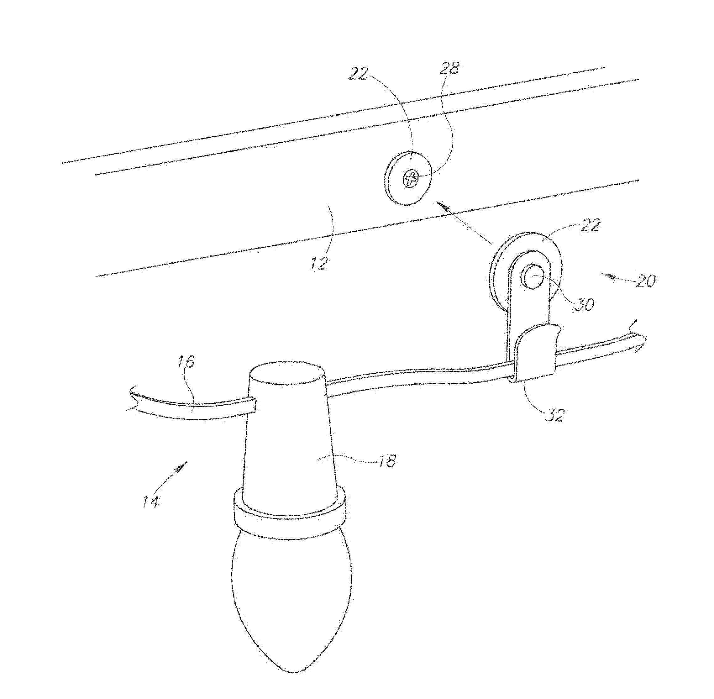
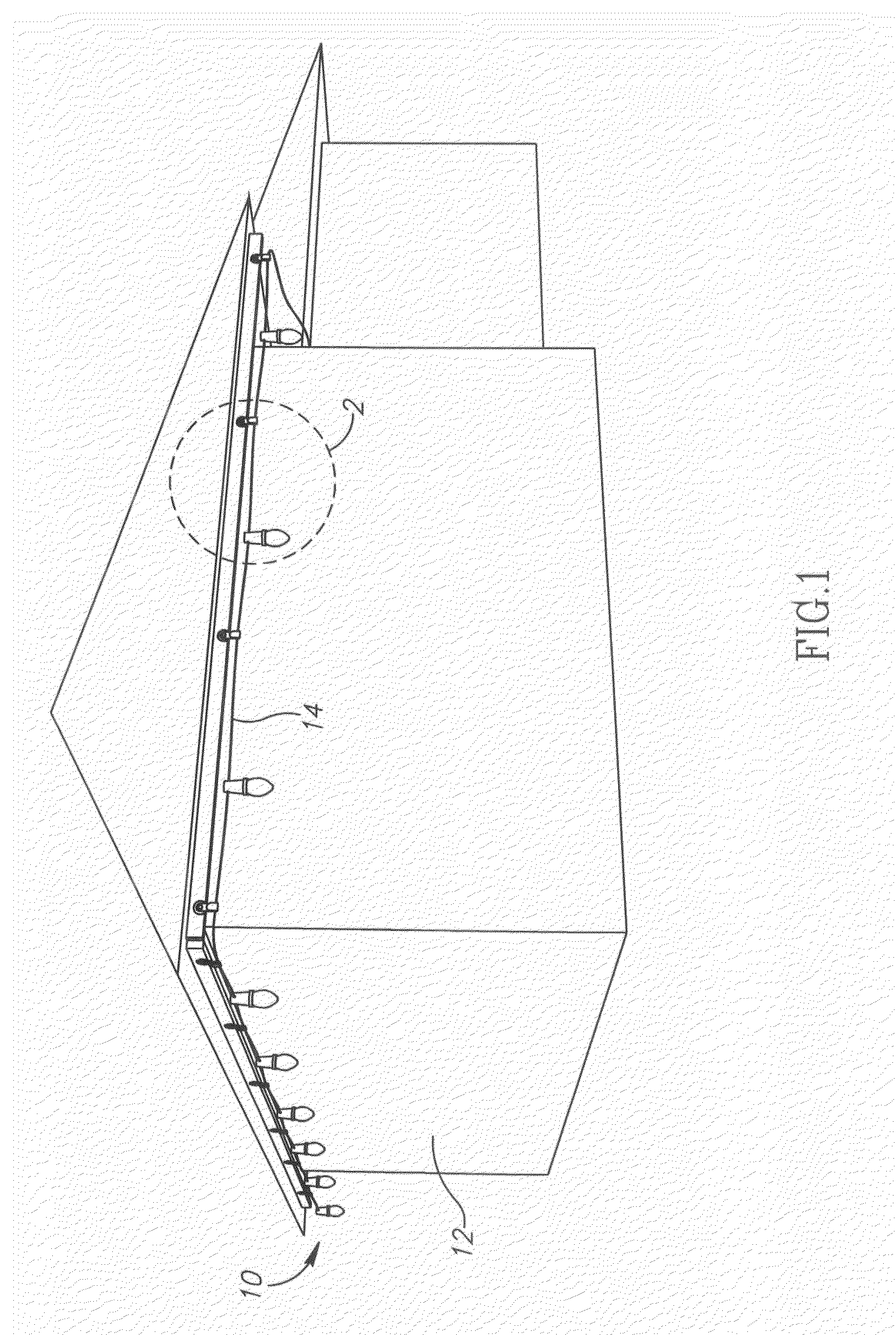
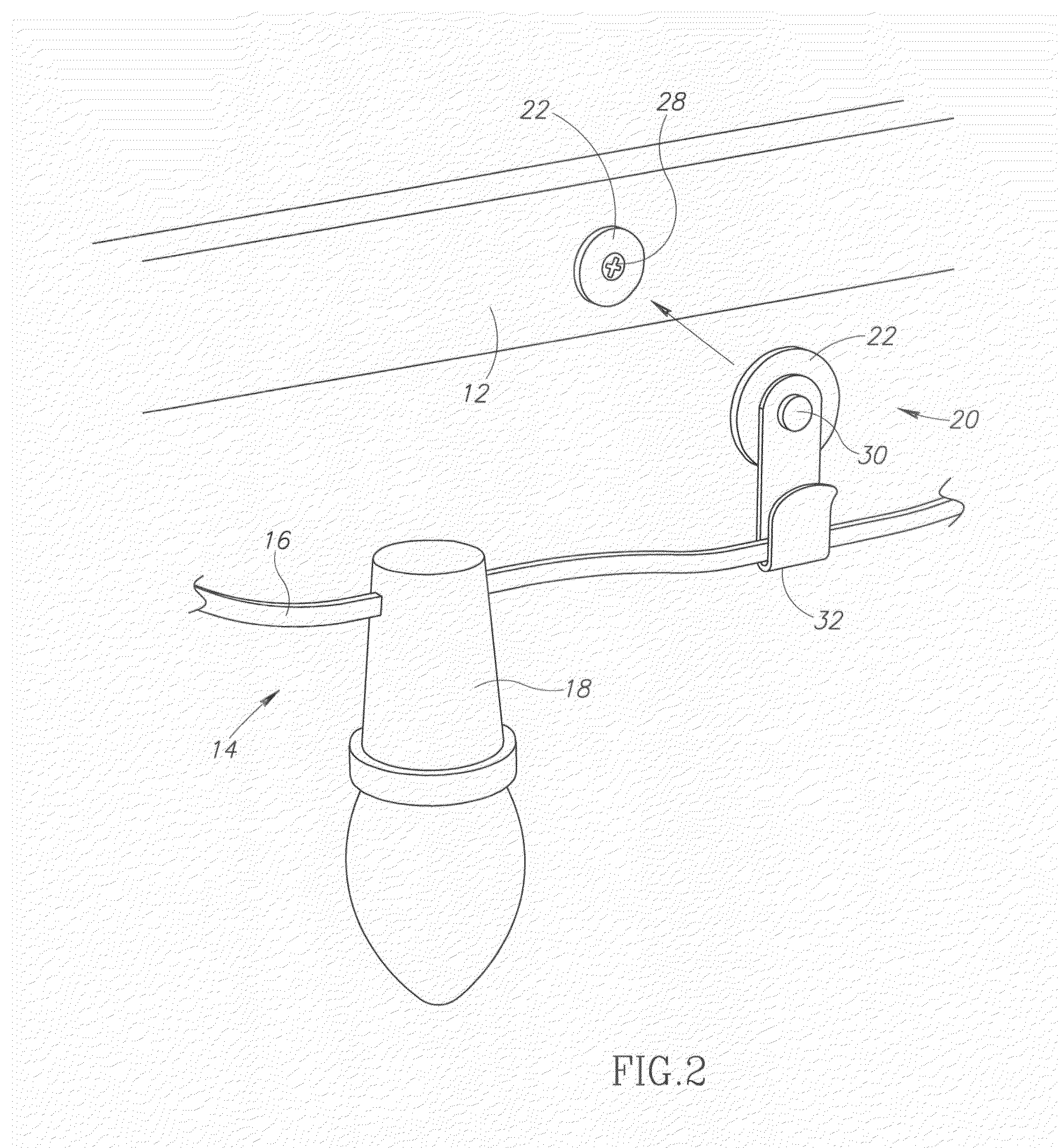
[0017]As illustrated in FIG. 1, a decorative light hanging system 10 for presenting a lighted outline of a building structure 12. The system 10 includes a strand of decorative lights 14 removably attached to the building structure 12 by a plurality of releasable magnetic alignment holder pairs 20 wherein a hanger 40 positions the pairs of releasable magnetic alignment holders 20 on the building structure 12.

[0018]A typical decorative light strand 14 in associ...


PUM


Abstract

The present invention provides a decorative light hanging system for presenting a lighted outline of a building structure, and includes a decorative lighting strand, a plurality of releasable magnetic alignment holder pairs each pair comprising oppositely charged magnetic disks including a first disk attached to the building structure and a second disk with a conduit mount attached thereon for receiving the decorative lighting strand therein, and a hanger for positioning and aligning the second disks upon the corresponding first disks.

Description

FIELD OF THE INVENTION[0001]The present invention is directed towards a decorative light hanging system for presenting a lighted outline of a building structure.BACKGROUND OF THE INVENTION[0002]It has long been desirable to hang decorative lights on a building structure during the holiday season as well as at other times of the year. Many solutions have been proposed regarding a means for temporarily securing a decorative light strand to a building structure. Simple solutions such as driving screws, nails or staples into the building structure upon which the strand rests or is held by have been improved upon by those seeking to minimize the number of holes created in the building structure in a single use and on consecutive uses and to maximize the consistency of the display on each consecutive use.[0003]Some of these improvements have involved the use of clips that can attach to eaves and guttering. The outline to be presented on the building structure, however, is generally not li...

Claims


Application Information

Patent Timeline
IPC IPC(8): F16M13/02F16B45/00
CPCF16B45/00F16B2001/0035F21W2121/004F21V17/105F21S4/001F21S4/10F16B2200/83
Inventor RINCK, LANCE
Owner RINCK LANCE
Why Eureka
Try Eureka