Non-metallic expansion/deflection coupling modules

a coupling module and non-metallic technology, applied in the direction of adjustable joints, pipe elements, mechanical equipment, etc., can solve the problems of limited ability of couplings to adjust for axial expansion and contraction movements, prior known expansion and deflection couplings that do not offer an increase in movements, etc., to achieve increased range of motion, reduce inner diameter, and increase the effect of movemen

Active Publication Date: 2012-11-08
THOMAS & BETTS INT INC
View PDF11 Cites 4 Cited by
  • Summary
  • Abstract
  • Description
  • Claims
  • Application Information

AI Technical Summary

Benefits of technology

[0006]A new coupling device that allows greater range of motion is disclosed. The coupling device can accommodate axial expansion and contraction, as well as angular and parallel deflection. The claimed device is also capable of angular movements while expanding / contracting without resulting in a decreased inner diameter. The claimed device is constructed in a modular fashion such that additional couplings can be added to further increase the range of motion.

Problems solved by technology

However, at junctions where the two conduits do not line up perfectly, such as in instances of axial misalignment or parallel misalignment, angled couplings are required to join the conduit together.
Currently available couplings have limited ability to adjust for axial expansion and contraction movements.
Furthermore, prior known expansion and deflection couplings do not offer an increase in movements when being installed on site.

Method used


Image

  • Non-metallic expansion/deflection coupling modules
  • Non-metallic expansion/deflection coupling modules
  • Non-metallic expansion/deflection coupling modules

Examples


Embodiment Construction

[0018]The following detailed description is presented to enable any person skilled in the art to make and use the invention. For purposes of explanation, specific details are set forth to provide a thorough understanding of the present invention. However, it will be apparent to one skilled in the art that these specific details are not required to practice the invention. Descriptions of specific applications are provided only as representative examples. Various modifications to the preferred embodiments will be readily apparent to one skilled in the art, and the general principles defined herein may be applied to other embodiments and applications without departing from the scope of the invention. The present invention is not intended to be limited to the embodiments shown, but is to be accorded the widest possible scope consistent with the principles and features disclosed herein.

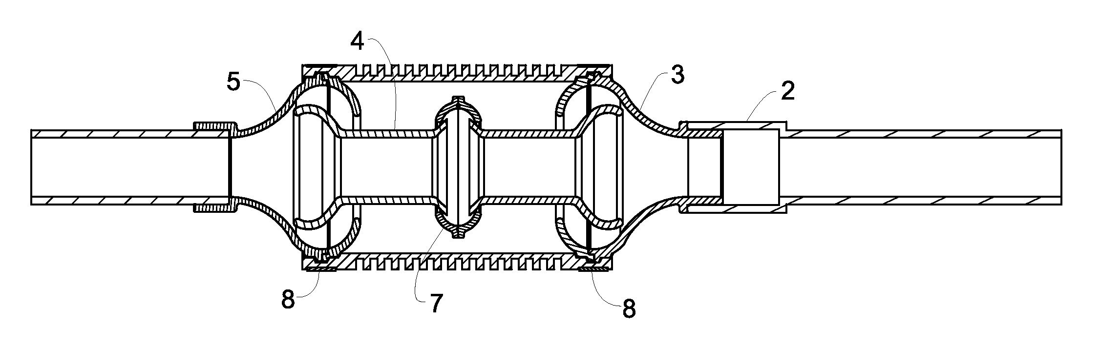
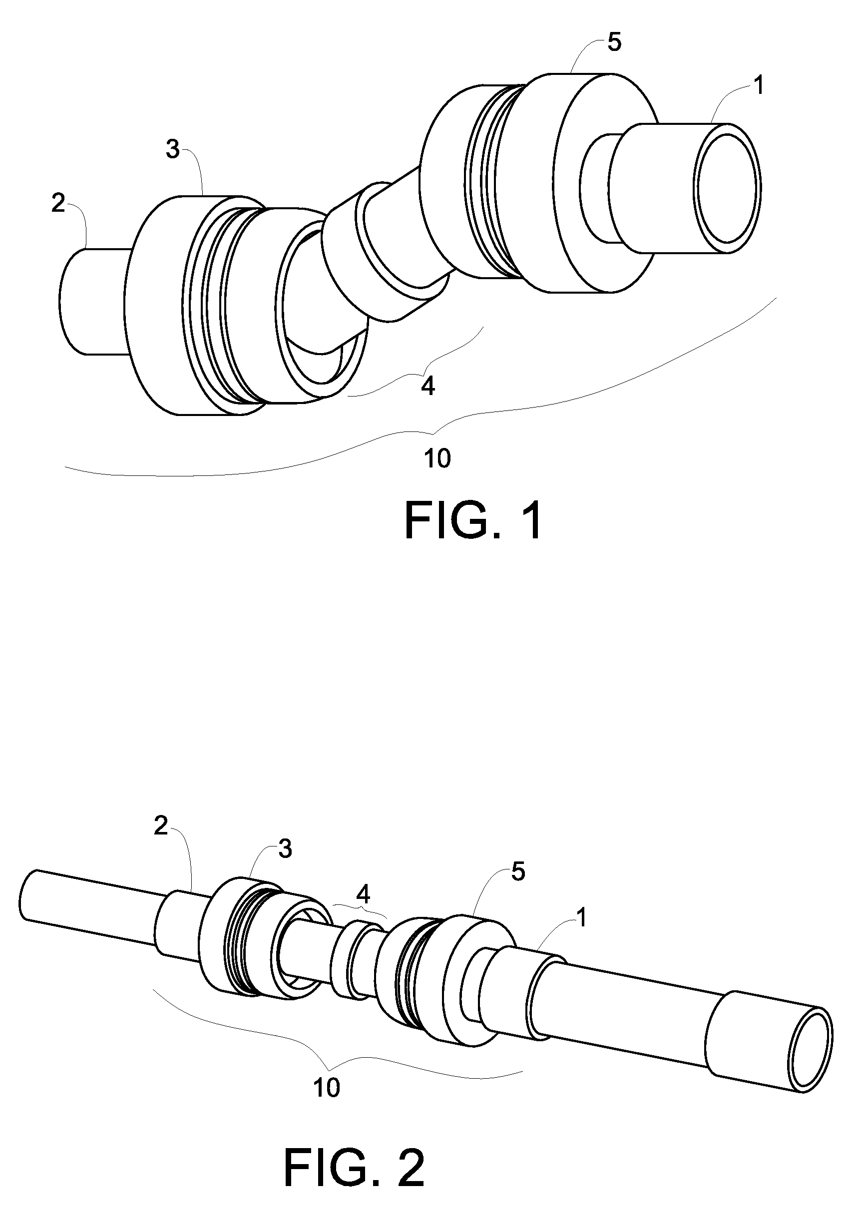
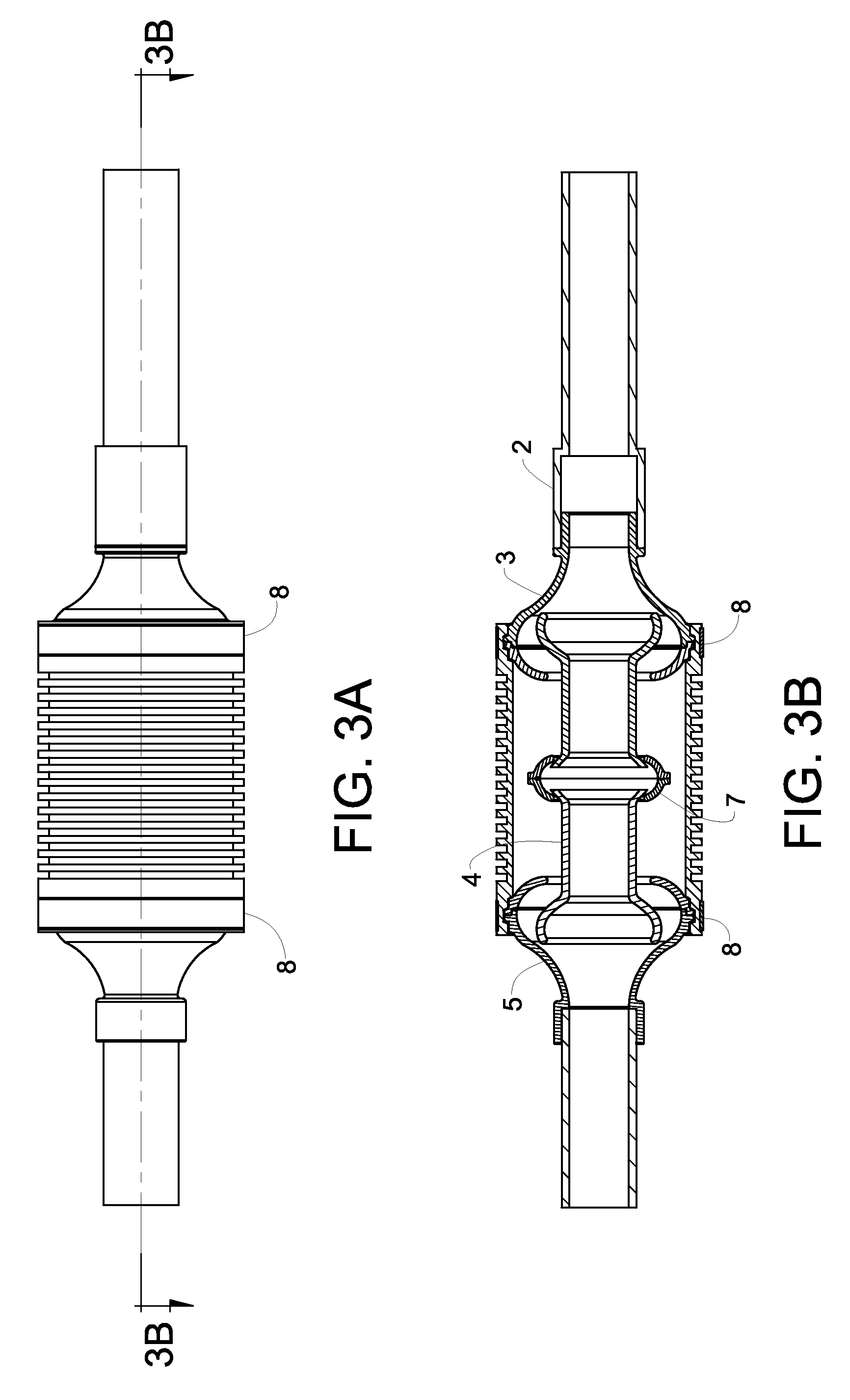
[0019]Referring to the drawings, FIG. 1 illustrates one embodiment of the invention. The device consist...


PUM

PropertyMeasurementUnit
angleaaaaaaaaaa
rigidaaaaaaaaaa
axial or angular movementaaaaaaaaaa

Abstract

An improved device for coupling rigid non-metallic conduits is disclosed. The claimed device is capable of allowing movement in an axial direction due to expansion and contraction and can also compensate for angular or parallel deflection of the conduits.

Description

CROSS-REFERENCES TO RELATED APPLICATIONS[0001]This application claims the benefit of U.S. Provisional Application No. 61 / 482,497 filed May 4, 2011, incorporated herein by reference in entirety.FIELD OF THE INVENTION[0002]The present invention is generally directed toward a device for joining electrical conduits. More specifically, it is directed toward an expansion and deflection coupling that allows a greater range of movement of the conduits relative to each other.BACKGROUND OF THE INVENTION[0003]When joining two pieces of electrical conduit together, a simple straight coupling is sufficient if the conduits are in axial alignment, and a rigid connection is acceptable. However, at junctions where the two conduits do not line up perfectly, such as in instances of axial misalignment or parallel misalignment, angled couplings are required to join the conduit together.[0004]Certain installations further require that the coupling be flexible in order to accommodate movement. For example...

Claims


Application Information

Patent Timeline
Patent Type & Authority Applications(United States)
IPC IPC(8): F16L27/00F16L55/00
CPCF16L27/026F16L47/18F16L27/00F16L27/0849F16L51/025
Inventor JAFFARI, ANDY ALI
Owner THOMAS & BETTS INT INC
Why Eureka
Try Eureka