
Inductor having different currents for different loads

Inactive Publication Date: 2012-11-08
MAG LAYERS SCI TECHNOICS
View PDF1 Cites 1 Cited by
  • Summary
  • Abstract
  • Description
  • Claims
  • Application Information

AI Technical Summary

Benefits of technology

[0008]The primary objective of the present invention is to provide an inductor including different saturation currents, such as a lower current for a lower load and a greater current for a greater load, for allowing the inductor to be suitably used in various kinds of apparatuses or facilities or the like.
[0012]The base device includes a slot formed therein for receiving or engaging with the terminals of the side elements for further solidly and stably anchoring or securing or retaining the conductive device to the base device and for preventing the conductive device from being disengaged from the base device.

Problems solved by technology

However, the typical inductors may only induce or generate a limited current that may not be suitably supplied to do work and that may include an increased or greater direct current resistance such that the generated current may not suitably flow through the typical inductors.

Method used


Image

  • Inductor having different currents for different loads
  • Inductor having different currents for different loads
  • Inductor having different currents for different loads

Examples


Embodiment Construction

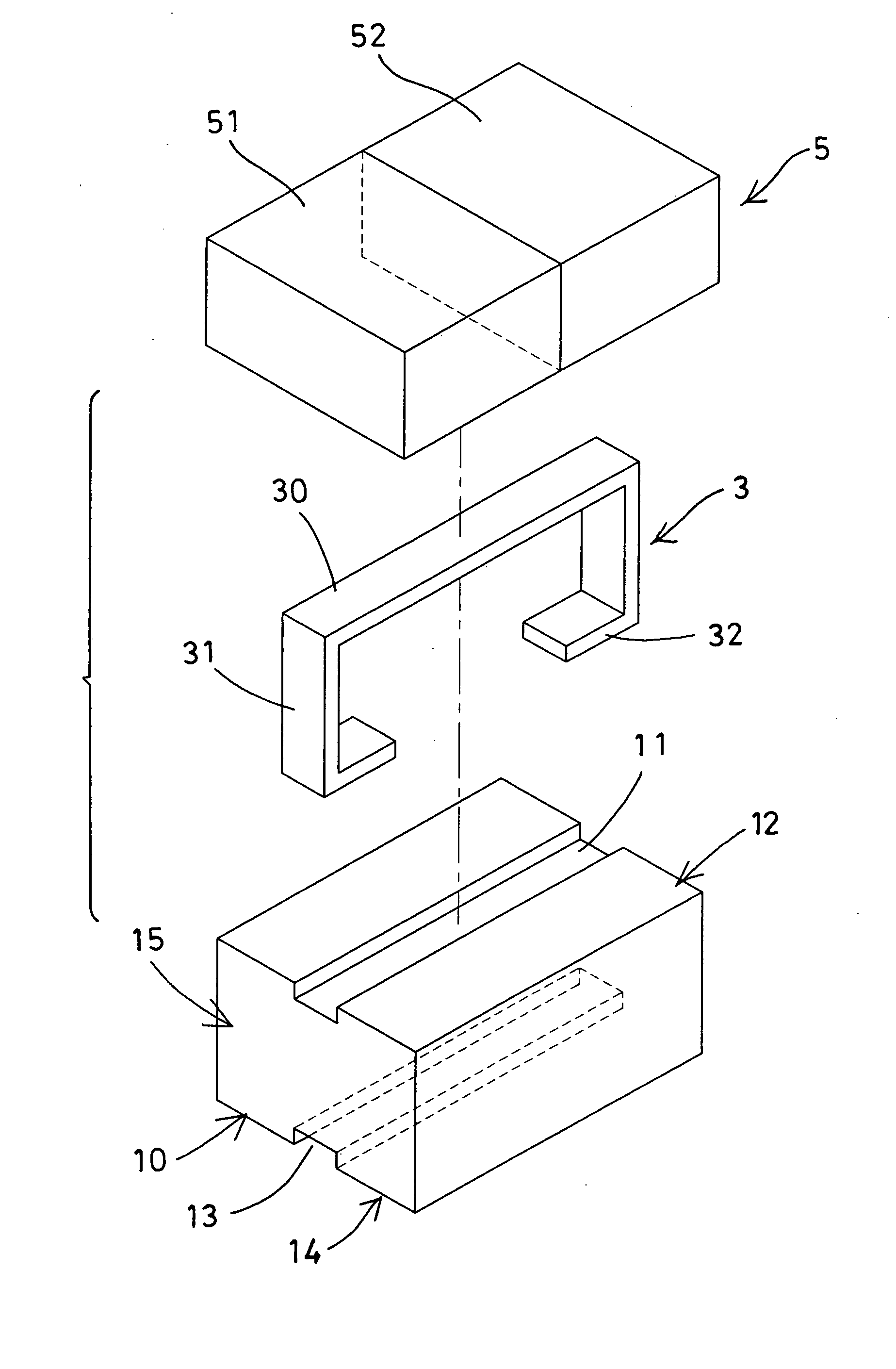
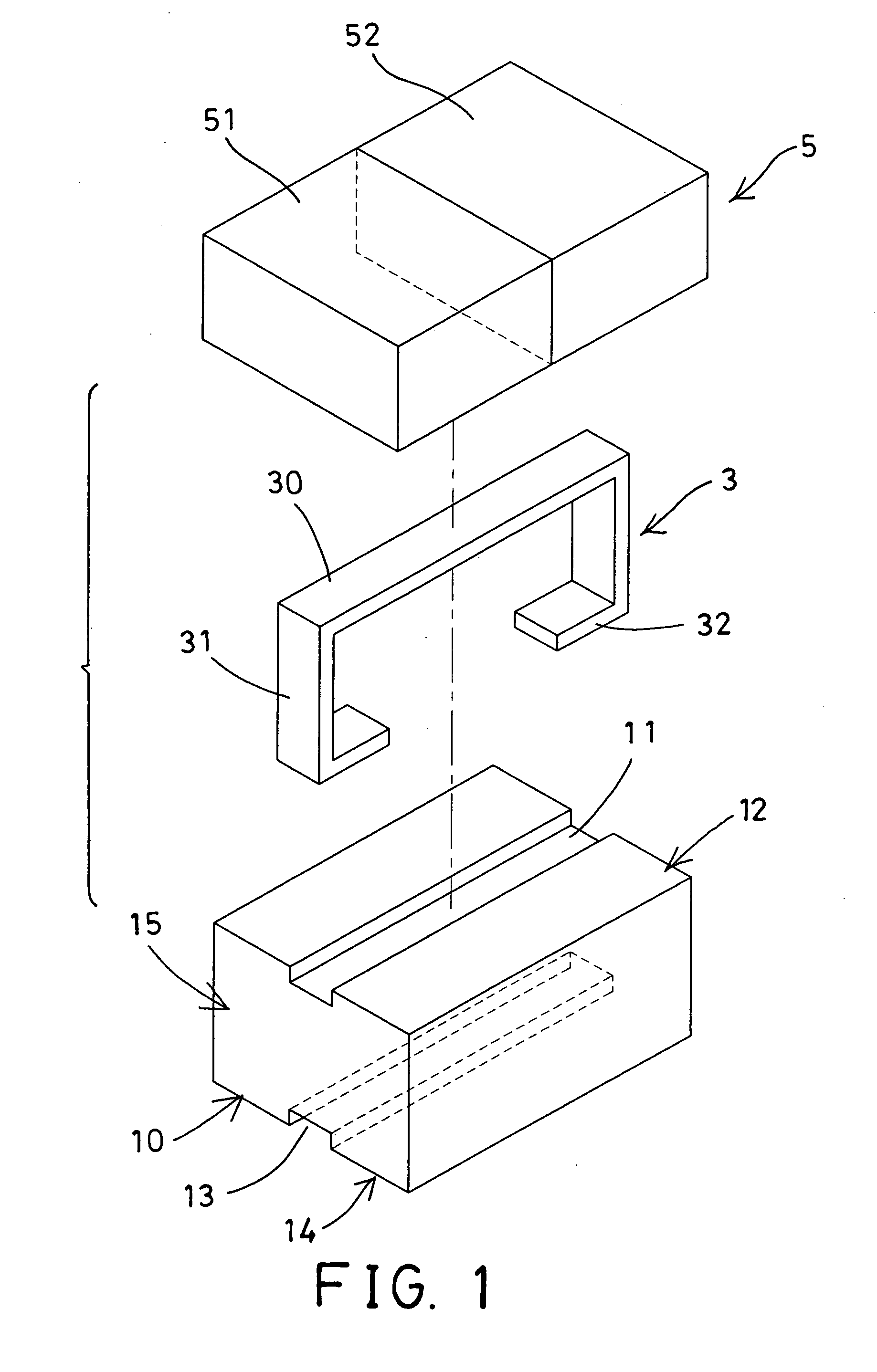
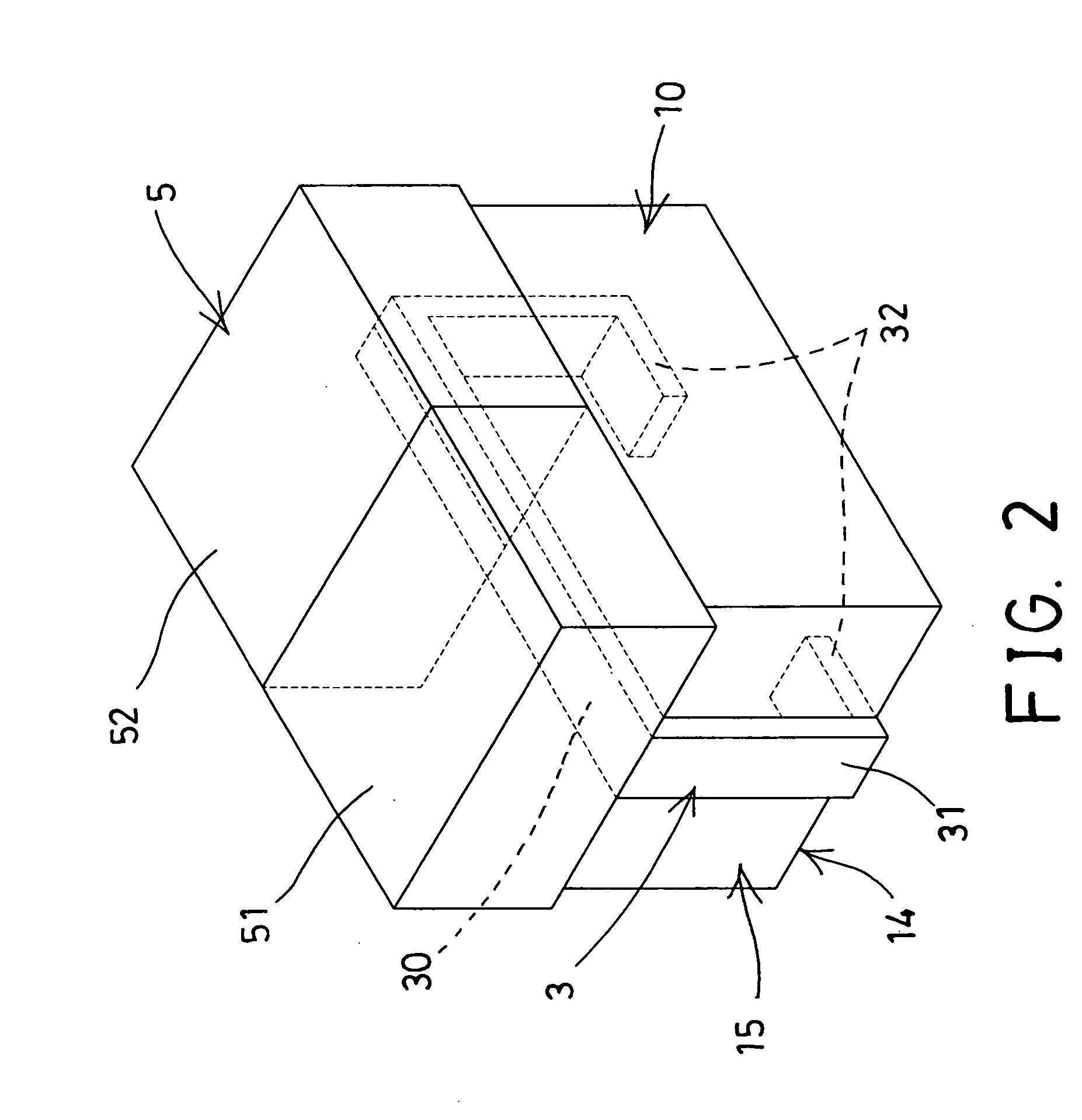
[0020]Referring to the drawings, and initially to FIGS. 1-2, an inductor in accordance with the present invention comprises a first or lower core or base device 10 including a longitudinal upper or first groove or channel 11 formed or provided on the upper portion 12 thereof, and including another longitudinal lower or second groove or slot 13 formed or provided on the lower portion 14 thereof, in which the upper channel 11 and the lower slot 13 of the base device 10 each include a depth or height smaller than the width of the upper channel 11 and the lower slot 13 of the base device 10 respectively.

[0021]A conductive device 3 is further provided and includes a central linking conductive bar or beam or element 30 having a size or dimension for snugly fitting or attaching or mounting or engaging into the upper channel 11 of the base device 10 for suitably increasing the saturation current and for allowing the inductor to be suitably used in various kinds of apparatuses or facilities ...


PUM


Abstract

An inductor includes a base device having a channel, a conductive device having a conductive element engaged into the channel of the base device and having two terminals, and a top device attached onto the base device and engaged with the base device, the top device includes two or more top members engaged with each other. The conductive device includes two side elements extended from the conductive element for engaging onto two end portions of the base device, and the terminals of the conductive device are extended from the side elements of the conductive device respectively. The base device includes a slot for receiving or engaging with the terminals of the side elements.

Description

BACKGROUND OF THE INVENTION[0001]1. Field of the Invention[0002]The present invention relates to an inductor, and more particularly to an inductor including different saturation currents, such as a lower current for a lower load and a greater current for a greater load, for allowing the inductor to be suitably used in various kinds of apparatuses or facilities or the like.[0003]2. Description of the Prior Art[0004]Typical inductors have been developed and provided for inducing the current and comprise one or more cores and one or more coils or conductive members for inducing or generating the current.[0005]For example, U.S. Pat. No. 5,751,203 to Tsutsumi et al., and U.S. Pat. No. 7,042,324 to Watanabe disclose two of the typical inductors each also comprising one or more coils or conductive members engaged into the cores for inducing or generating the current.[0006]However, the typical inductors may only induce or generate a limited current that may not be suitably supplied to do wo...

Claims


Application Information

Patent Timeline
IPC IPC(8): H01F27/29
CPCH01F27/29H01F38/023H01F27/266H01F27/263H01F27/292H01F27/306
Inventor LU, HANG CHUNYANG, YA WENYEH, HSIU FACHEN, PIN YU
Owner MAG LAYERS SCI TECHNOICS
Features
  • Generate Ideas
  • Intellectual Property
  • Life Sciences
  • Materials
  • Tech Scout
  • Unparalleled Data Quality
  • Higher Quality Content
  • 60% Fewer Hallucinations
Learn More