
Laser scan unit for an imaging device

a scanning unit and imaging device technology, applied in the field of electrographic devices having laser scanning units, can solve the problems of design being more susceptible to characteristics, affecting the quality of imaged sheets, and affecting the quality of halftoned images, so as to reduce scan jitter and scan line variability.

Active Publication Date: 2012-11-08
LEXMARK INT INC
View PDF4 Cites 6 Cited by
  • Summary
  • Abstract
  • Description
  • Claims
  • Application Information

AI Technical Summary

Benefits of technology

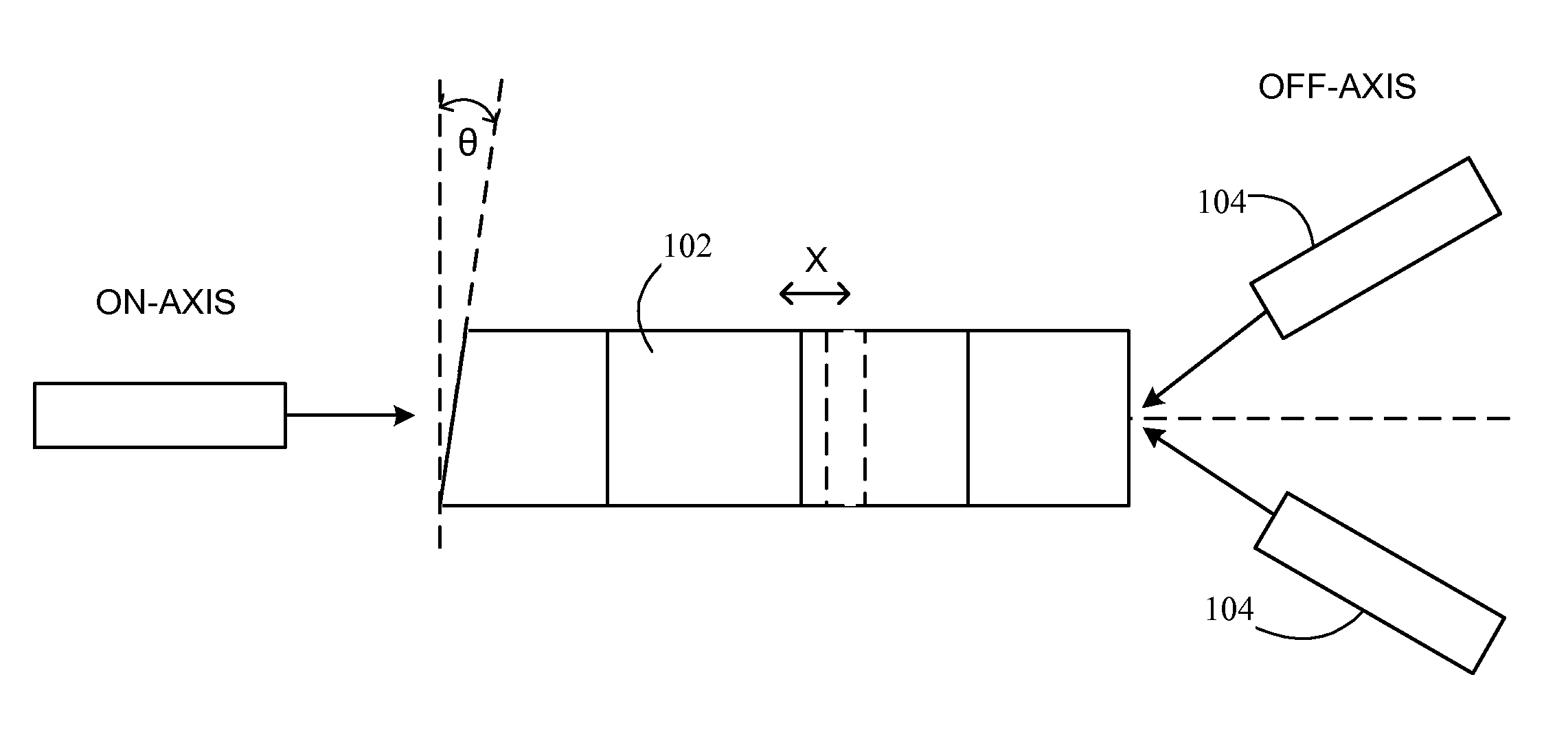
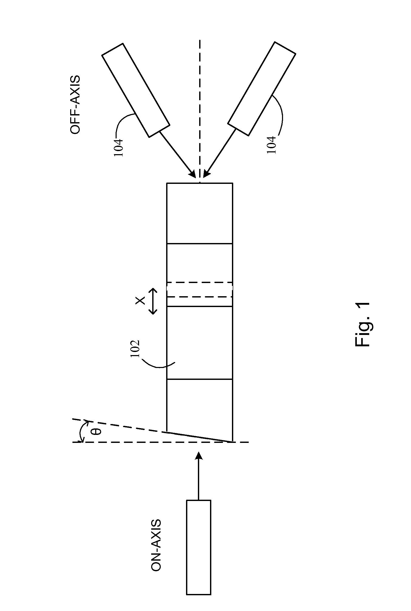
[0011]Example embodiments overcome the shortcomings of prior systems and thereby satisfy a significant need for a scanning system which reduces scan jitter and scan line variability on a facet-to-facet basis utilizing an off-axis laser scanning architecture. Example embodiments may apply to LSUs having synchronization sensors associated with each laser channel as well as to LSU's having a synchronization sensor associated with a single channel while other channels image off of other mirror facets. In general terms, facet timing information is maintained in system memory at time of manufacture, and the imaging device performs similar facet timing measurements and matches the measured facet timing with the stored facet timing information to substantially correct scan line length and jitter based upon the match.

Problems solved by technology

There are some characteristics associated with laser scanning systems which adversely impact the quality of an imaged sheet.
When jitter and scan line length variation occur, halftoned images can experience a degraded quality especially when using higher lines per inch (LPI) halftone screens.
Such off-axis architectures result in the design being more susceptible to the characteristics mentioned above.

Method used


Image

  • Laser scan unit for an imaging device
  • Laser scan unit for an imaging device
  • Laser scan unit for an imaging device

Examples


Embodiment Construction

[0021]The following description and drawings illustrate embodiments sufficiently to enable those skilled in the art to practice it. It is to be understood that the subject matter of this application is not limited to the details of construction and the arrangement of components set forth in the following description or illustrated in the drawings. The subject matter is capable of other embodiments and of being practiced or of being carried out in various ways. For example, other embodiments may incorporate structural, chronological, electrical, process, and other changes. Examples merely typify possible variations. Individual components and functions are optional unless explicitly required, and the sequence of operations may vary. Portions and features of some embodiments may be included in or substituted for those of others. The scope of the application encompasses the appended claims and all available equivalents. The following description is, therefore, not to be taken in a limit...


PUM


Abstract

A system and method for reducing scan line jitter in laser scan systems employing a rotating mirror, including a controller for determining a unique time delay for each mirror facet and controlling laser sources so that video provided by each laser source is delayed in a scan line by the unique time delay corresponding to the mirror facet used in creating the scan line. The controller computes a facet map signature vector corresponding to each mirror facet matches the signature to a previously stored signature and assigns distance offset data to the mirror facets based upon the matching.

Description

CROSS REFERENCES TO RELATED APPLICATIONS[0001]Pursuant to 35 U.S.C. §119, this application claims the benefit of the earlier filing date of Provisional Application Ser. No. 61 / 483,635, filed May 6, 2011, entitled “Laser Scan Unit for an Imaging Device,” the content of which is hereby incorporated by reference herein in its entirety.BACKGROUND[0002]1. Technical Field[0003]The present application relates generally to electronic devices having a laser scan unit (LSU), and particularly to an improved electrophotographic devices having reduced jitter and scan line variability for off-axis based LSU systems.[0004]2. Description of the Related Art[0005]Laser scanning systems, such as those utilized in color electrophotographic imaging devices, typically include a plurality of laser sources, each of which generates a laser beam containing data to be imaged onto a media sheet, a rotating polygonal mirror from which the laser beams reflect such that each beam impinges on a distinct photocondu...

Claims


Application Information

Patent Timeline
Patent Type & Authority Applications(United States)
IPC IPC(8): G03G13/04G03G15/043
CPCG03G15/04072G02B26/10G03G2215/0145
Inventor CHEN, FEIHADADY, CRAIG ERICJONES, CHRISTOPHER DANELEMASTER, JOHN
Owner LEXMARK INT INC
Learn More