

Gripper attachment for robot
- Summary
- Abstract
- Description
- Claims
- Application Information
AI Technical Summary
Benefits of technology
Problems solved by technology
Method used
Image

Examples
Embodiment Construction
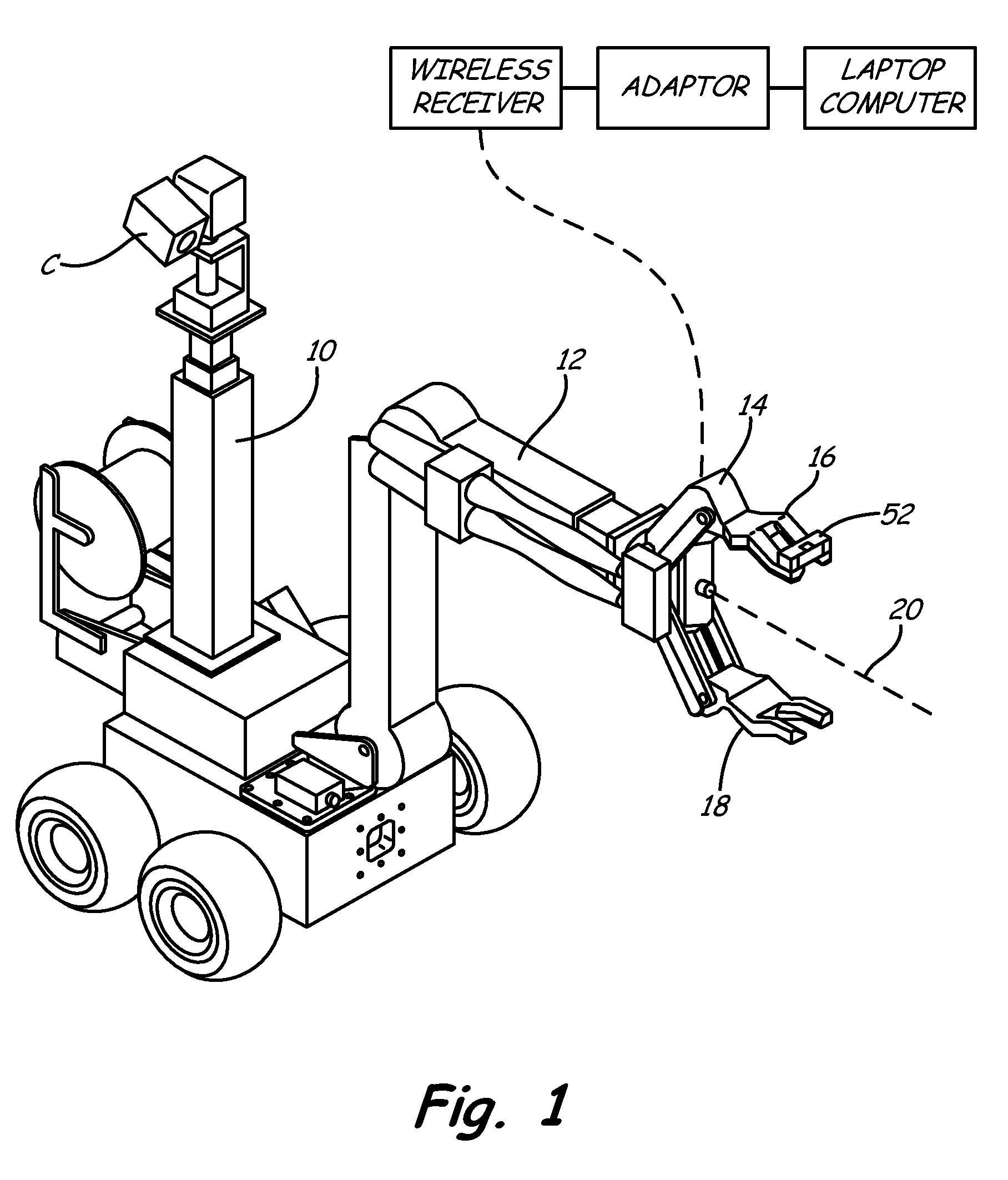
[0020]Depicted in FIG. 1 is a conventional robot 10. As illustrated, robot 10 happens to be a Remotec® (REMOTEC, INC., Oak Ridge, Tenn.) ANDROS F6A (Northrup Grumman Information Services), but it will be appreciated that any comparable or similar robotic device, such as those used for law enforcement, public safety, military, or paramilitary applications, may be employed. Robot 10 comprises an articulated arm 12. Mounted at the distal end of arm 12 is an end effector, or gripper, 14. Via means that are conventional and well known in the art, gripper 14 is in electronic, hydraulic and / or physical communication with, and is operably connected to, arm 12. Video camera C mounted on robot 10 views gripper 14 and provides images for use by operator.
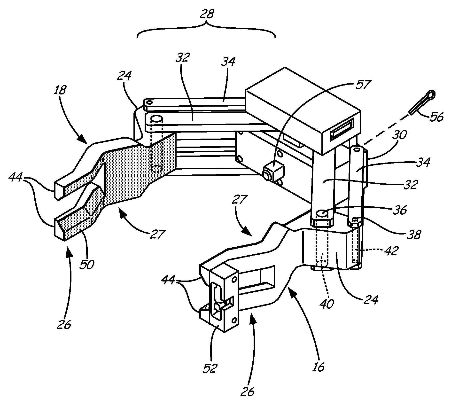
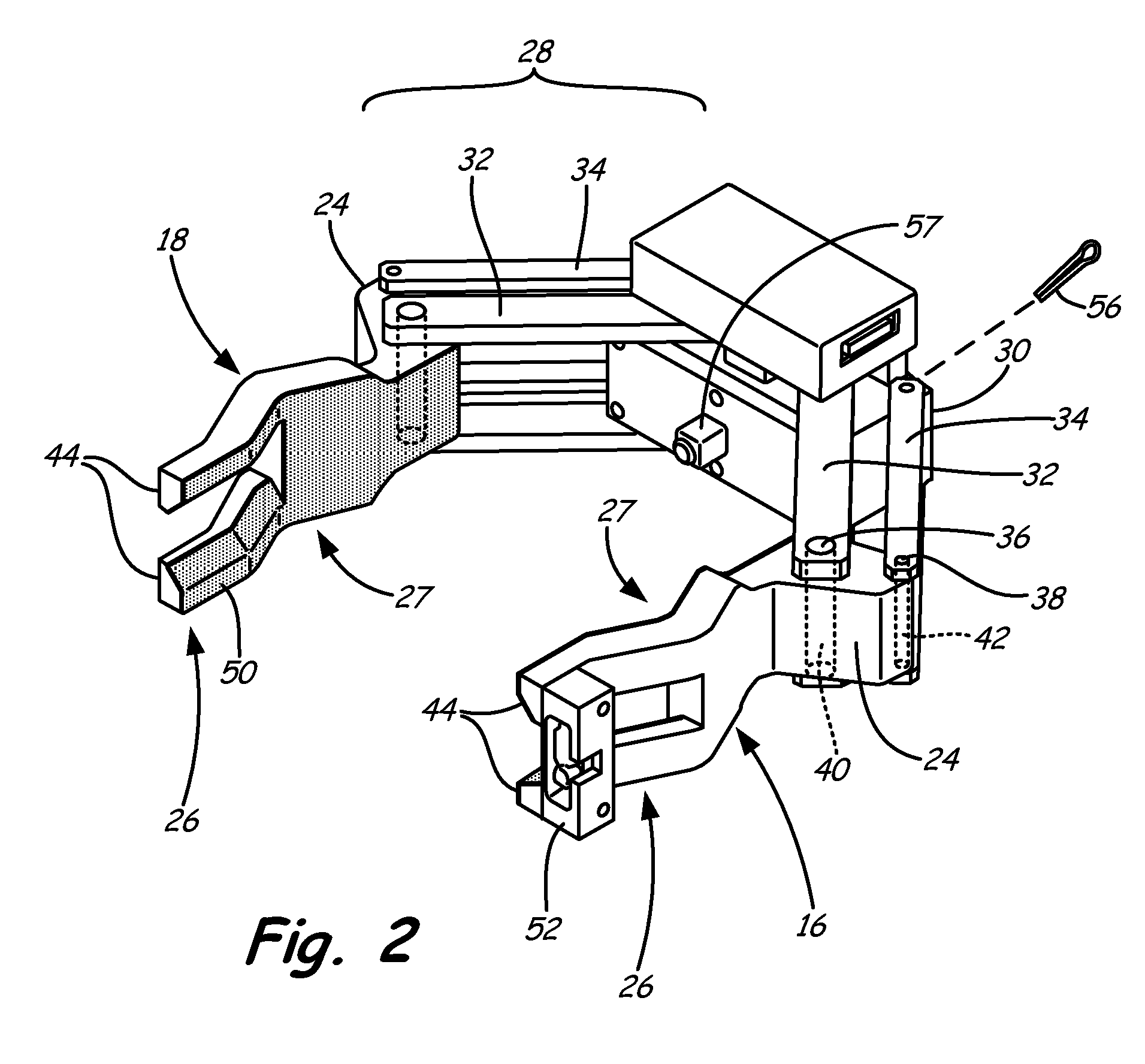
[0021]Turning to FIG. 2, gripper 14 further comprises a first claw member 16 and a second claw member 18 opposed and symmetric to first claw member 16. Claw members 16, 18 are preferably identical or substantially similar in size and compositio...
PUM
 Abstract
Description
Claims
Application Information