
Method for creating an inner thread as well as a combination of a thread cutter and a body having a cutout

a cutting tool and cutting body technology, applied in the direction of threaded fasteners, forging/pressing/hammering apparatuses, forging/hammering/pressing machines, etc., can solve the problem of requiring a great deal of force in cutting threads, and achieve the effect of reducing the amount of for

Active Publication Date: 2012-11-15
HILTI AG
View PDF3 Cites 6 Cited by
  • Summary
  • Abstract
  • Description
  • Claims
  • Application Information

AI Technical Summary

Benefits of technology

[0006]It is an object of the present invention to reduce the amount of force required for cutting such a thread.
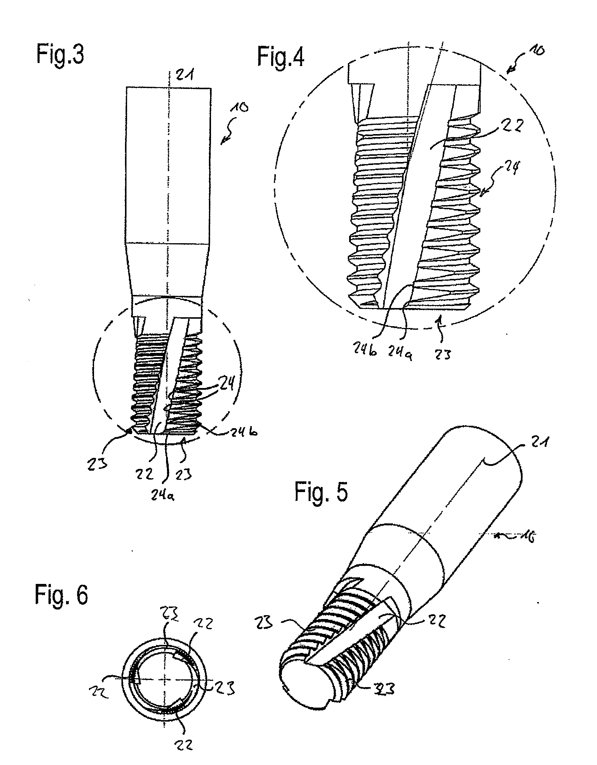
[0007]The present invention provides a thread cutter, which has an axial lengthwise cutout adjacent to which in the circumferential direction there are blades that project radially outwards and that have cutting edges, whereby several cutting edges arranged one after the other in the longitudinal direction are provided on the lengthwise cutout, and they are offset with respect to each other in the circumferential direction. When the cutting tool is rotated by a maximum of 360° in order to create the entire inner thread in the projection, the cutting edges penetrate into the projection one after the other as the thread cutter turns. This has the advantage that, at first, only one or a few cutting edges are in contact with the projection and cut their way into it. Only once these cutting edges have cut their way into the projection do additional cutting edges come into contact with the projection and cut their way into it. The force increase as the tool is turned takes place more slowly and more uniformly, so that large force peaks can be avoided, especially at the beginning of the cutting procedure. Since the force needed for a cutting edge to cut into the material is greatest at the beginning of the cutting procedure and since these load peaks caused by the individual cutting edges are distributed, the maximum force needed to cut the thread is considerably less than in the case of a conventional thread cutter.
[0008]The cylindrical opening or the cutting tool is preferably configured in such a way that the thread cutter is inserted into the opening in a rectilinear movement, that is to say, no rotational movement is made while the thread cutter is being inserted, so that this procedure is simple and fast. The thread cutter only needs to be aligned at the beginning of the procedure in such a way that the cutting edges can be pushed into the grooves. Subsequently, the thread cutter is completely inserted into the opening with a rectilinear movement, then turned and finally pulled out of the opening, likewise with a rectilinear movement.
[0009]As an alternative, the groove of the opening can also run helically in the opening and, when the thread cutter is being inserted, it is turned so as to follow the groove, whereby especially the cutting edges do not come into contact with the opening while they are being inserted. As a result, the interruption of a thread track created by the groove is offset in the circumferential direction, so that the load from a load-transmission means screwed into the body can be more effectively transmitted to the entire circumference of the opening. The offset of the cutting edges in the circumferential direction is selected here in such a manner that their curvature differs from that of the groove, so that here, too, the cutting edges do not simultaneously come into contact with the projection, and they penetrate into the projection one after the other.
[0012]The thread cutter can also have several lengthwise cutouts that are offset in the circumferential direction. In such an embodiment, the opening has a corresponding number of projections. This makes it possible to form a complete thread even with less of a rotation. If, for example, two lengthwise cutouts are provided which are situated opposite from each other, a turn of 180° can create a complete thread in the appertaining body that has two grooves corresponding to the lengthwise cutouts. The turning of the cutting tool can be further reduced with a corresponding number of uniformly distributed grooves.

Problems solved by technology

A problematic aspect of this production technique is that it requires a great deal of force in order to cut the thread.

Method used


Image

  • Method for creating an inner thread as well as a combination of a thread cutter and a body having a cutout
  • Method for creating an inner thread as well as a combination of a thread cutter and a body having a cutout
  • Method for creating an inner thread as well as a combination of a thread cutter and a body having a cutout

Examples


Embodiment Construction

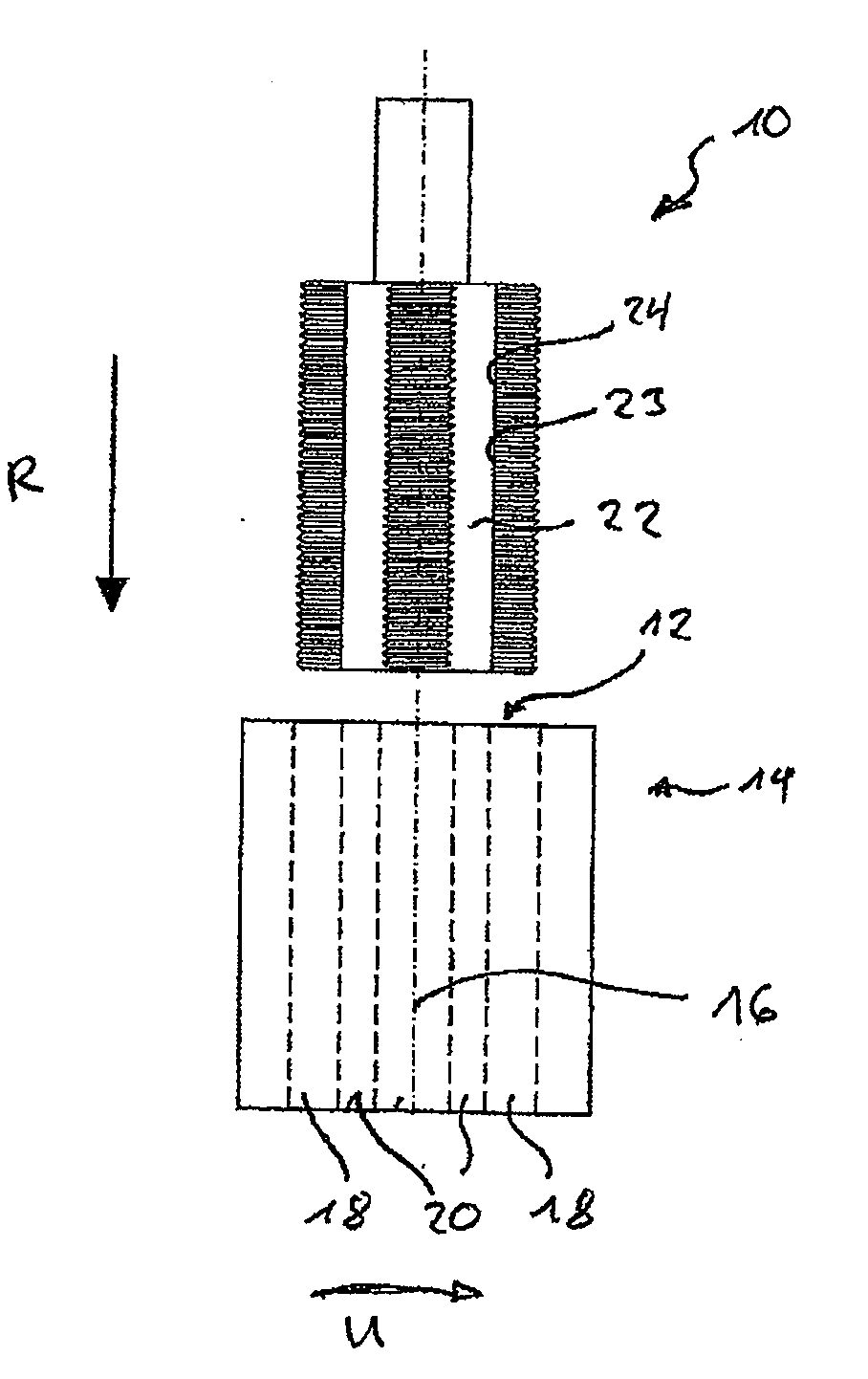
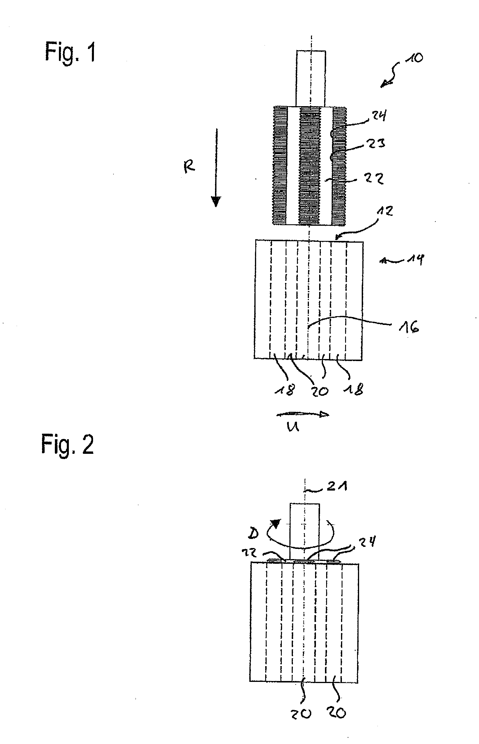
[0028]FIGS. 1 and 2 show a conventional thread cutter 10 for cutting an inner thread in a hole-like opening 12 of a body 14. The hole-like opening 12 is configured essentially cylindrically and has a center axis16. Furthermore, the opening 12 has several axially running grooves 18 distributed uniformly along the inner circumference. As seen in the circumferential direction U, a radially inwards as well as axially running projection 20 is provided after each groove.

[0029]The depth of the grooves 18 as measured from the center axis 16 is equal to or greater than the outer radius of the desired thread and equal to or greater than the outer radius of the thread cutter 10.

[0030]The thread cutter 10 has a longitudinal axis 21 that coincides with the center axis 16 as well as several lengthwise cutouts 22 uniformly distributed along the outer circumference, whereby the number of lengthwise cutouts 22 matches the number of projections 20 of the body 14. In each case, a set of cutting edges ...


PUM

PropertyMeasurementUnit
rotationaaaaaaaaaa
rotational angleaaaaaaaaaa
depthaaaaaaaaaa

Abstract

A method for creating an inner thread in an opening of a body, using a thread cutter, including the following steps:a) the thread cutter having an axial lengthwise cutout adjacent to which there are blades that project radially outwards and that have cutting edges, is inserted into the opening, whereby several cutting edges arranged one after the other in the longitudinal direction are provided on the lengthwise cutout, which are offset with respect to each other in the circumferential direction, and which are pushed into the groove when the thread cutter is being inserted,b) the cutting tool is rotated by a maximum of 360° in order to create the entire inner thread in at least one projection next to the groove, whereby the cutting edges penetrate into the projection one after the other as the thread cutter turns, andc) the thread cutter is moved axially out of the opening.

Description

[0001]This claims the benefit of German Patent Application DE 10 2011 075 770.8 filed May 12, 2011, and hereby incorporated by reference herein.BACKGROUND[0002]The invention relates to a method for using a thread cutter in order to create an inner thread in an essentially cylindrical opening of a body having a center axis, whereby the cylindrical opening has at least one groove that runs essentially in the longitudinal direction, whose depth is equal to or greater than the outer radius of the thread cutter as measured from the center axis, whereby a projection that extends radially inwards and axially is provided in the body after the groove as seen in the circumferential direction. Moreover, the invention relates to a combination of a thread cutter and a body having a cylindrical opening with at least one groove that runs essentially in the longitudinal direction.[0003]Various production methods are known for purposes of creating an inner thread in the opening of a body, for exampl...

Claims


Application Information

Patent Timeline
Patent Type & Authority Applications(United States)
IPC IPC(8): B21D53/24B23D77/00B23G1/00
CPCB23G1/16Y10T408/9048B23G5/06B23G7/02
Inventor FLOETER, FELIX
Owner HILTI AG
Learn More