Paraplegia prevention valve for stent grafts

a technology of paraplegia and stent graft, which is applied in the field of medical devices, can solve problems such as inability to catheteris

Active Publication Date: 2012-11-15
COOK MEDICAL TECH LLC
View PDF3 Cites 25 Cited by
  • Summary
  • Abstract
  • Description
  • Claims
  • Application Information

AI Technical Summary

Problems solved by technology

There are also a number of other minor side branch arteries but these are smaller

Method used


Image

  • Paraplegia prevention valve for stent grafts
  • Paraplegia prevention valve for stent grafts
  • Paraplegia prevention valve for stent grafts

Examples


first embodiment

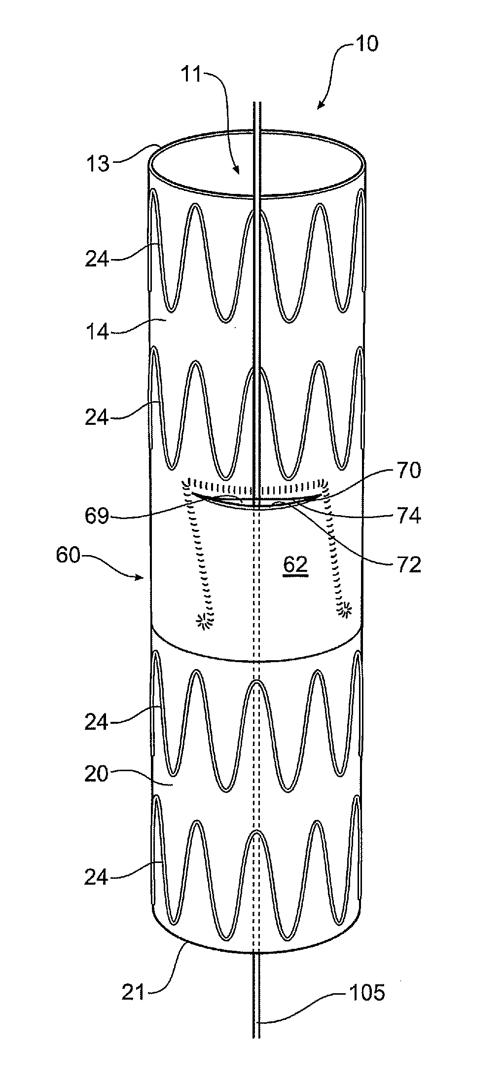
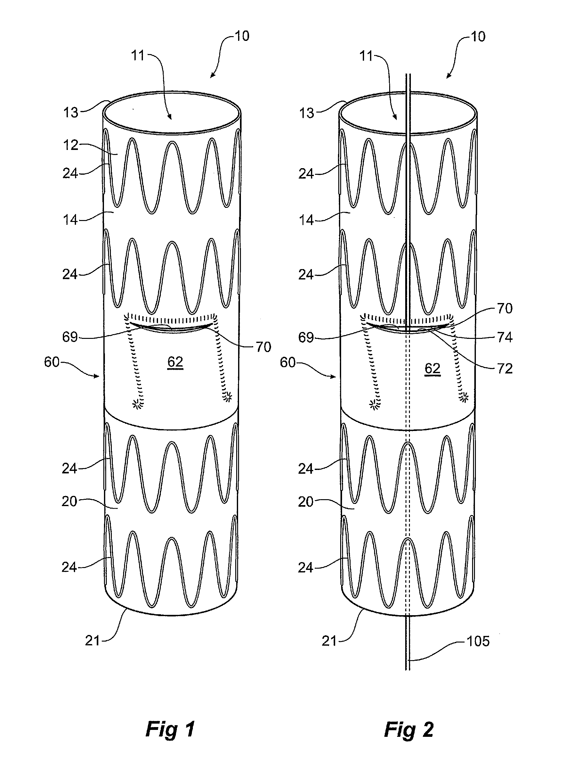
[0033]FIG. 1 shows a perspective view of a stent graft according to the invention;

[0034]FIG. 2 is a similar view to that of FIG. 1 but shows the stent graft pre-loaded with a wire;

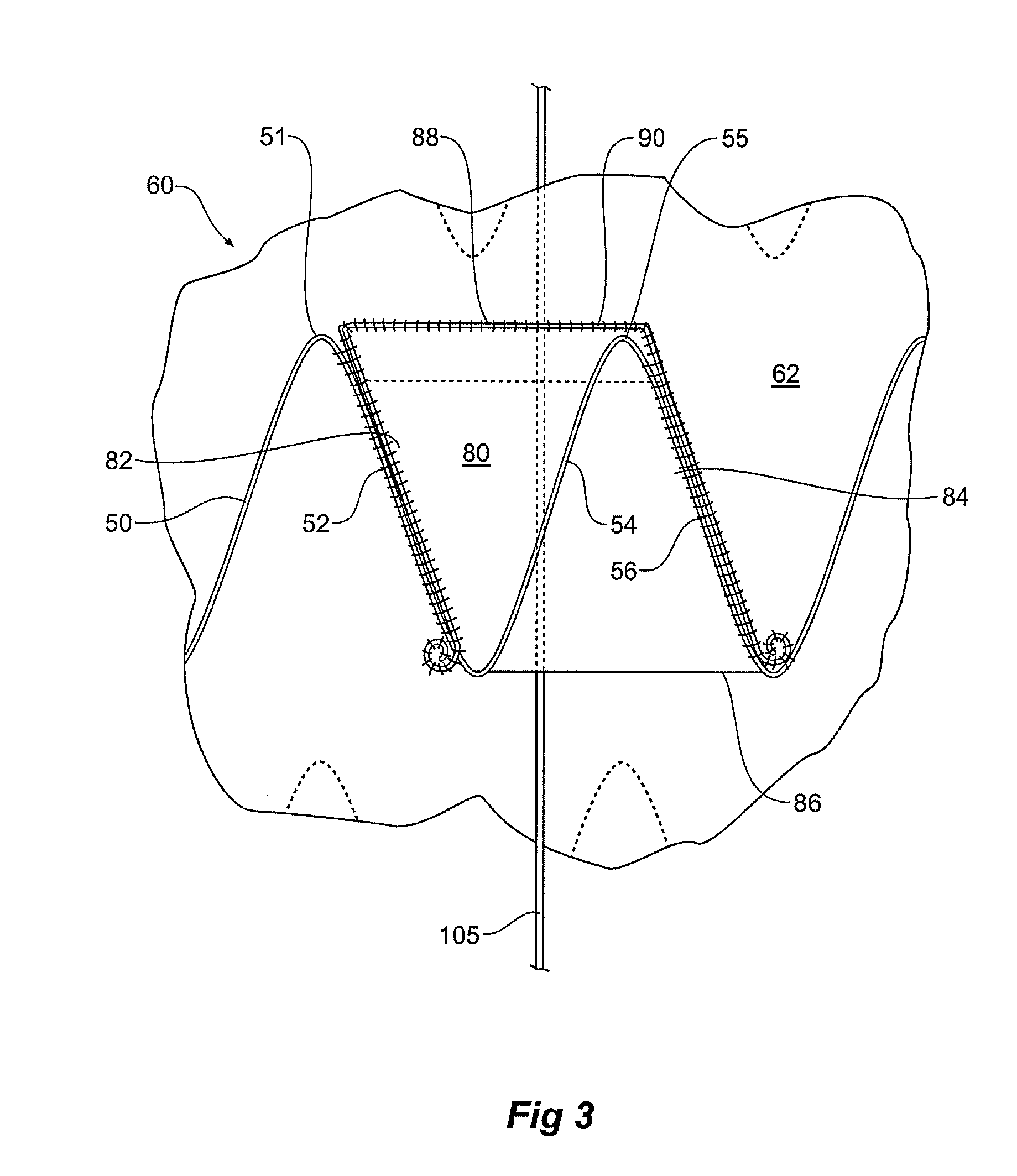
[0035]FIG. 3 shows a detailed view of a portion of the inside of the stent graft shown in FIG. 2;

[0036]FIG. 4a shows a perspective cut-away view of the stent graft of FIG. 2;

[0037]FIG. 4b is the same view as that of FIG. 4a, but with a wire removed;

[0038]FIG. 5 is a similar view to that of FIG. 4a but shows a valve of stent graft in an open condition;

second embodiment

[0039]FIG. 6 shows a perspective view of a stent graft according to the invention;

[0040]FIG. 7 is a similar view to that of FIG. 6 but shows the stent graft pre-loaded with a wire;

[0041]FIG. 8 shows a detailed view of a portion of the inside of the stent graft shown in FIG. 7;

[0042]FIG. 9 shows a perspective cut-away view of the stent graft of FIG. 7;

third embodiment

[0043]FIG. 10 shows a detailed view of a portion of the inside of the stent graft shown in FIG. 7, the stent graft which has an alternative valve arrangement;


PUM


Abstract

A stent graft defining a main lumen bounded by a wall of graft material is disclosed. The stent graft has a valve portion between proximal and distal portions. The valve portion is formed by a wall portion having a part-circumferential double layer portion comprising an inner underlap portion and an outer overlap portion, the double layer portion forming a passageway parallel to the main lumen. The passageway has an entrance mouth and an exit mouth. The passageway has an open condition where the underlap and overlap portions are spaced apart to form a vent lumen. The wall portion is broken by a narrow cut. The cut is openable by relative radial movement between its edges. This allows re-perfusion of an aneurism and perfusion of blood from within the lumen out towards blood vessels such as intercostals and can assist in minimising the chance of paraplegia.

Description

FIELD OF INVENTION[0001]This invention relates to a medical device and more particularly to an implantable endovascular device.BACKGROUND OF THE INVENTION[0002]This invention will be discussed in general with respect to aortic aneurysms and the use of an implantable device such as a stent graft to bridge an aneurysm and in particular in the descending aorta but the invention is not so limited and may be used for any region of the human or animal body and any type of implantable device.[0003]A stent graft can be used to bridge an aortic aneurysm but where there are side branch arteries from the aorta it is necessary to have side branches extending from the stent graft to give a blood supply to as many side branch arteries as possible.[0004]There are four main side branch arteries in the descending aorta. These are the celiac artery, the superior mesenteric artery, the right renal artery and the left renal artery. There are also a number of other minor side branch arteries but these a...

Claims


Application Information

Patent Timeline
IPC IPC(8): A61F2/06A61F2/84A61F2/07A61F2/954A61F2/958
CPCA61F2/07A61F2/954A61F2/958A61F2002/061A61F2230/0019A61F2250/0039A61F2/89A61F2002/075A61F2250/0037
Inventor IVANCEV, KRASNODARKASPRZAK, PIOTR MIROSLAWHARTLEY, DAVID ERNEST
Owner COOK MEDICAL TECH LLC
Why Eureka
Try Eureka