Eureka AIR delivers breakthrough ideas for toughest innovation challenges, trusted by R&D personnel around the world.

Variable inertia flywheel

Inactive Publication Date: 2012-11-22
GENERAL ELECTRIC CO
View PDF7 Cites 10 Cited by
  • Summary
  • Abstract
  • Description
  • Claims
  • Application Information

AI Technical Summary

Benefits of technology

[0007]According to one aspect, when the flywheel is installed and in operation in an engine system, the chambers are filled with a fluid when the engine is being idled at low speed. Conversely, the chambers are drained (or partially drained) of the fluid when the engine is being accelerated. Thus, flywheel and engine rotating inertia is large when the engine is being idled at low speed, but small when high engine torque response characteristics are required, such as when the engine is being accelerated. This minimizes the variations in engine speed caused by a change in the power load, while additionally providing an increased level of engine responsiveness.

Problems solved by technology

Thus, flywheel and engine rotating inertia is large when the engine is being idled at low speed, but small when high engine torque response characteristics are required, such as when the engine is being accelerated.

Method used


Image

  • Variable inertia flywheel
  • Variable inertia flywheel
  • Variable inertia flywheel

Examples


Embodiment Construction

[0017]Reference will be made below in detail to exemplary embodiments of the invention, examples of which are illustrated in the accompanying drawings. Wherever possible, the same reference numerals used throughout the drawings refer to the same or like parts. Although exemplary embodiments of the present invention are described with respect to marine vessels, embodiments of the invention are also applicable for use with work machines generally, meaning any truck, vehicle or other heavy machinery that utilizes an engine to provide power.

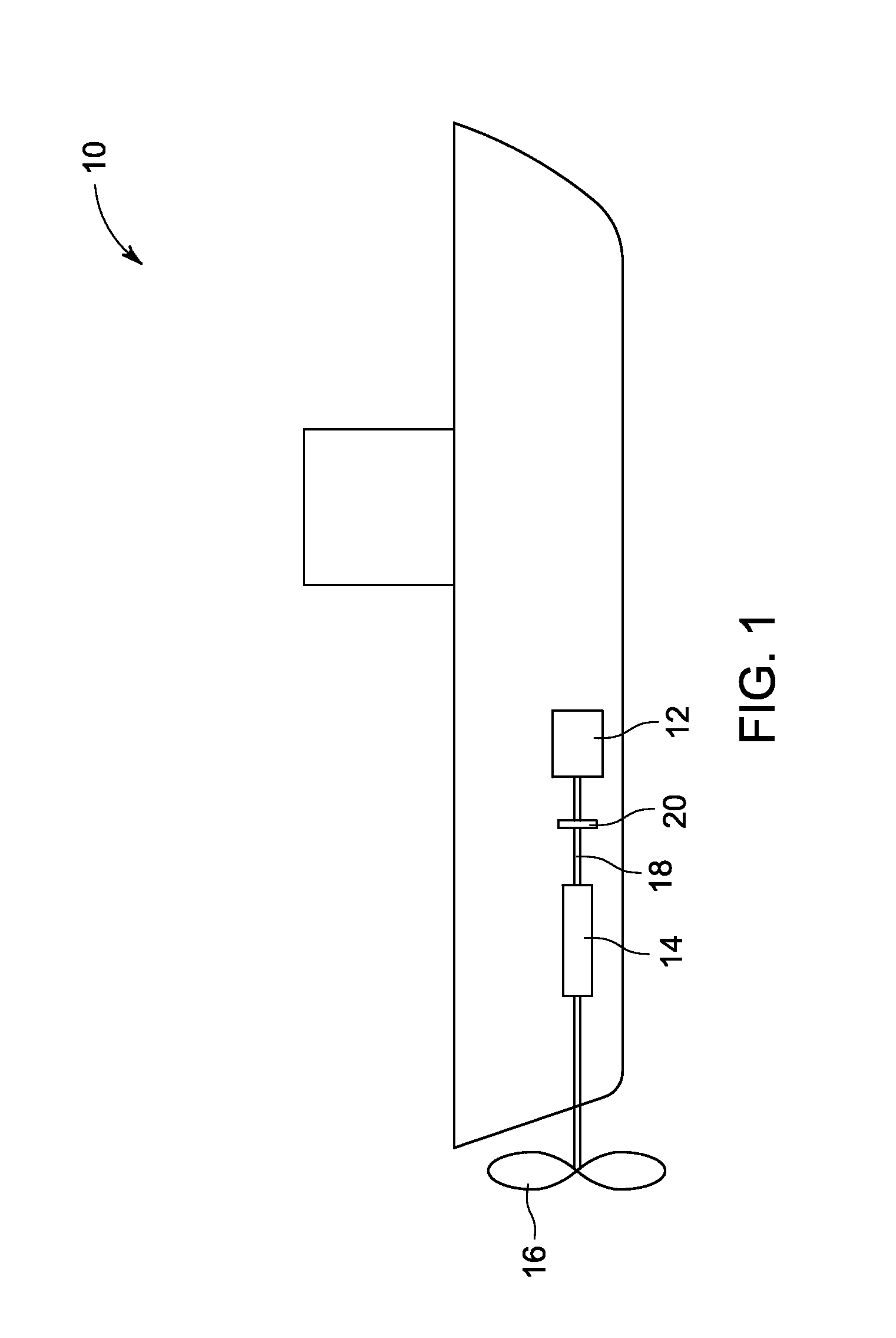
[0018]FIG. 1 is a schematic illustration of a marine vessel 10 in accordance with an embodiment of the present invention. As shown therein, the marine vessel 10 includes an engine 12 and a transmission 14 connected to a propulsion device of the marine vessel. In an embodiment, the propulsion device is at least one propeller 16. In an embodiment, the engine 12 is an internal combustion engine, such as a gasoline engine, diesel engine, or natural gas e...


PUM


Abstract

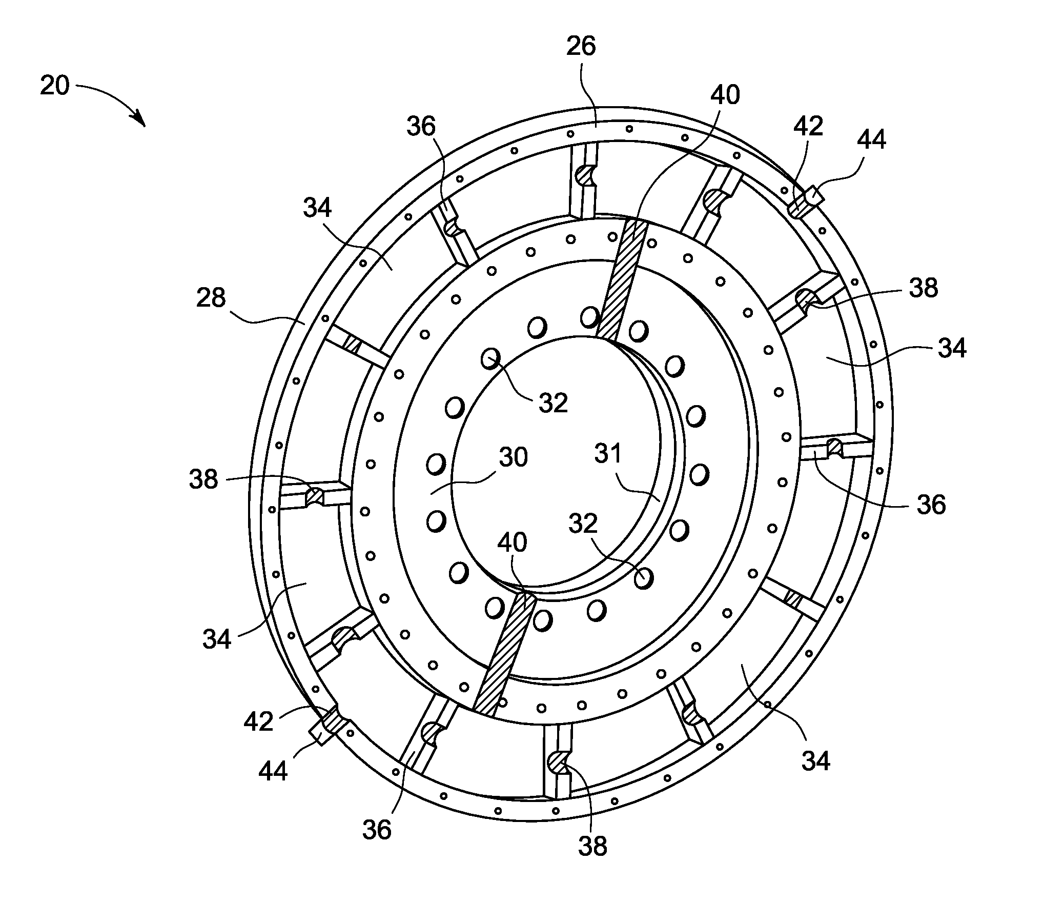
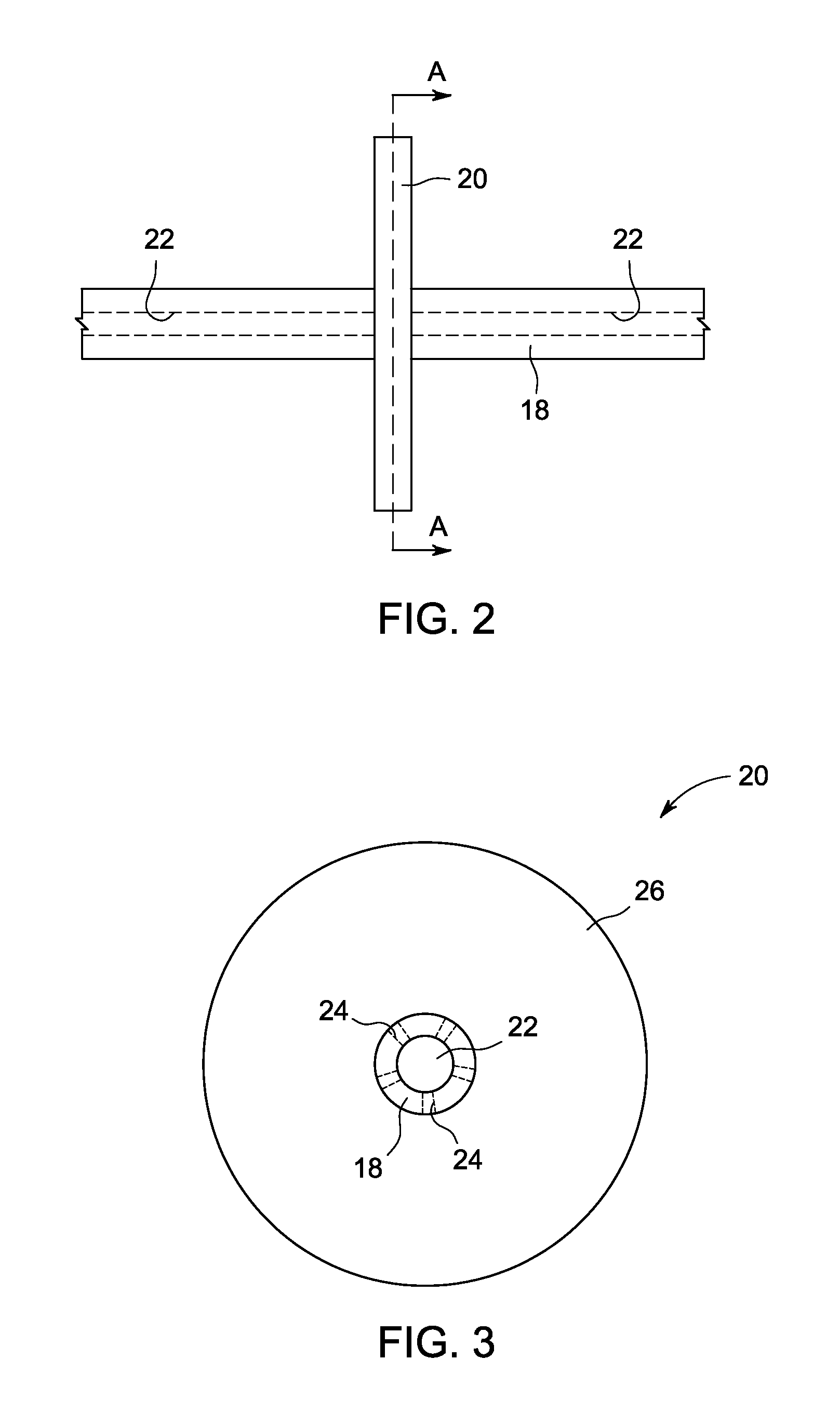
A flywheel includes a disc-shaped flywheel body having a peripheral surface defining a circumference of the flywheel body, a central hub connected to the body for mounting the flywheel on a crankshaft or other flywheel support, and a plurality of chambers in the flywheel body radially spaced from the central hub and angularly spaced about the circumference of the flywheel body.

Description

FIELD OF THE INVENTION[0001]Embodiments of the invention relate generally to flywheels and, more particularly, to flywheels for marine vessels.BACKGROUND OF THE INVENTION[0002]Vehicles and vessels, such as trucks, heavy machinery, and river-going ships and boats, are used for a variety of tasks. These vehicles and vessels may include a transmission coupled to an engine, such as an internal combustion engine, that provides the power to complete these tasks. The transmission may be mechanical, hydro-mechanical, hydraulic, or an electric transmission that transmits engine power to a traction device or, in the case of a marine vessel, a propeller. The power load placed on the transmission by the propeller or traction device is transmitted to the engine. Power load changes, either requiring additional power or less power, may cause the engine to deviate from a desired operating range. As will be readily appreciated, deviations from the desired speed range may result in poor efficiency, l...

Claims


Application Information

Patent Timeline
IPC IPC(8): F16F15/167F16F15/30
CPCF16F15/31Y10T74/2122Y10T74/2132
Inventor JAYAKAR, VIJAYASELVANDAS, SUMIT KUMAR
Owner GENERAL ELECTRIC CO
Why Eureka
Eureka Blog
Learn More