Organic electroluminescent light source

a light source and organic technology, applied in the field of light sources, can solve the problems of inability to meet the color rendering index failure of the conventional organic electroluminescent lamp to meet the manufacturer's needs,

Active Publication Date: 2012-11-22
AU OPTRONICS CORP
View PDF6 Cites 16 Cited by
  • Summary
  • Abstract
  • Description
  • Claims
  • Application Information

AI Technical Summary

Benefits of technology

[0007]The invention is directed to an organic electroluminescent light source having adaptive color temperature.

Problems solved by technology

Consequently, the conventional organic electroluminescent lamp fails to satisfy the manufacturer's needs when the manufacturer demands for light sources with high color temperature and low light intensity or light sources with low color temperature and high light intensity.
Further, the color rendering index of the conventional organic electroluminescent lamp can not meet the practical demand (that is, lower than 80).

Method used


Image

  • Organic electroluminescent light source
  • Organic electroluminescent light source
  • Organic electroluminescent light source

Examples


first embodiment

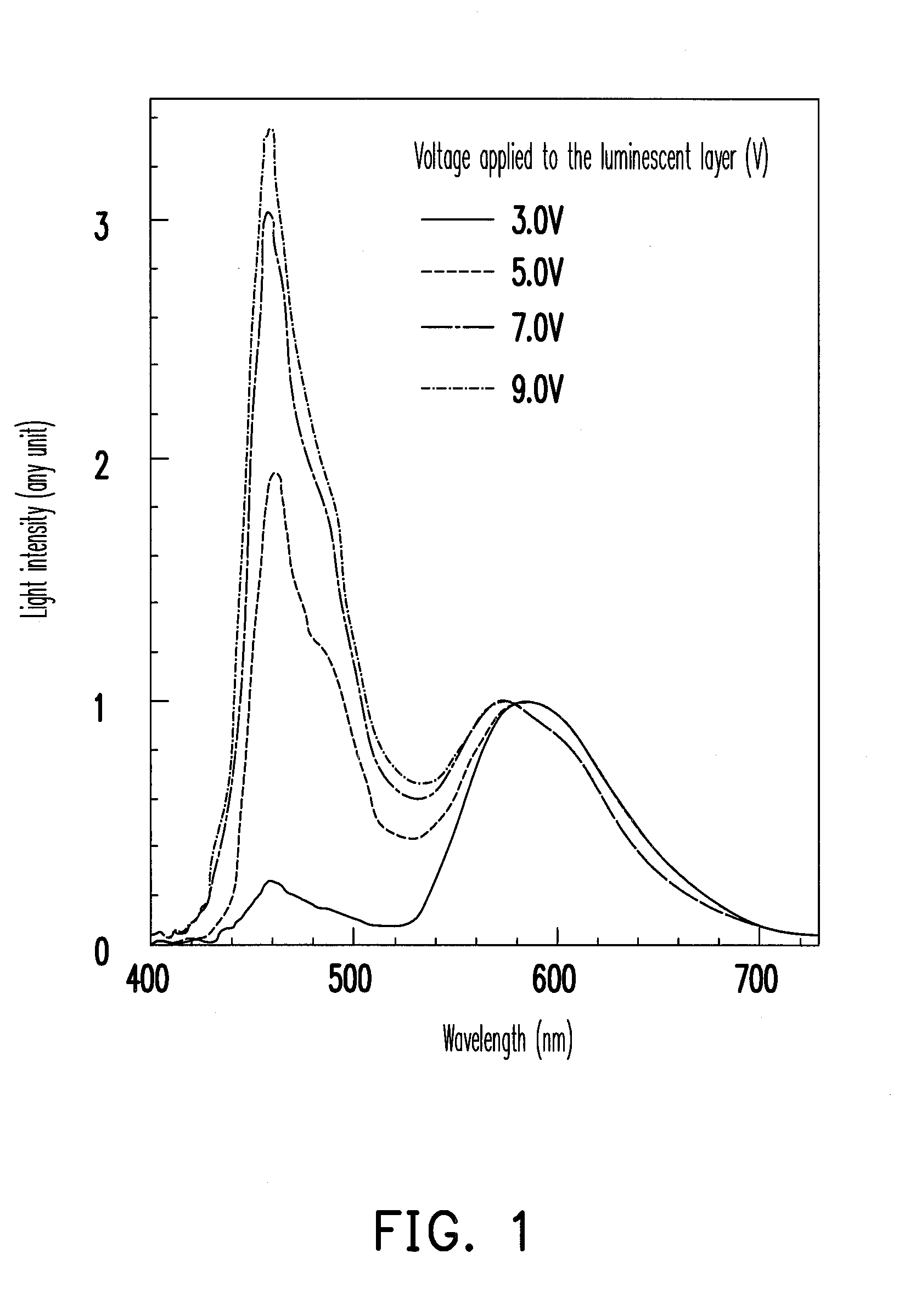
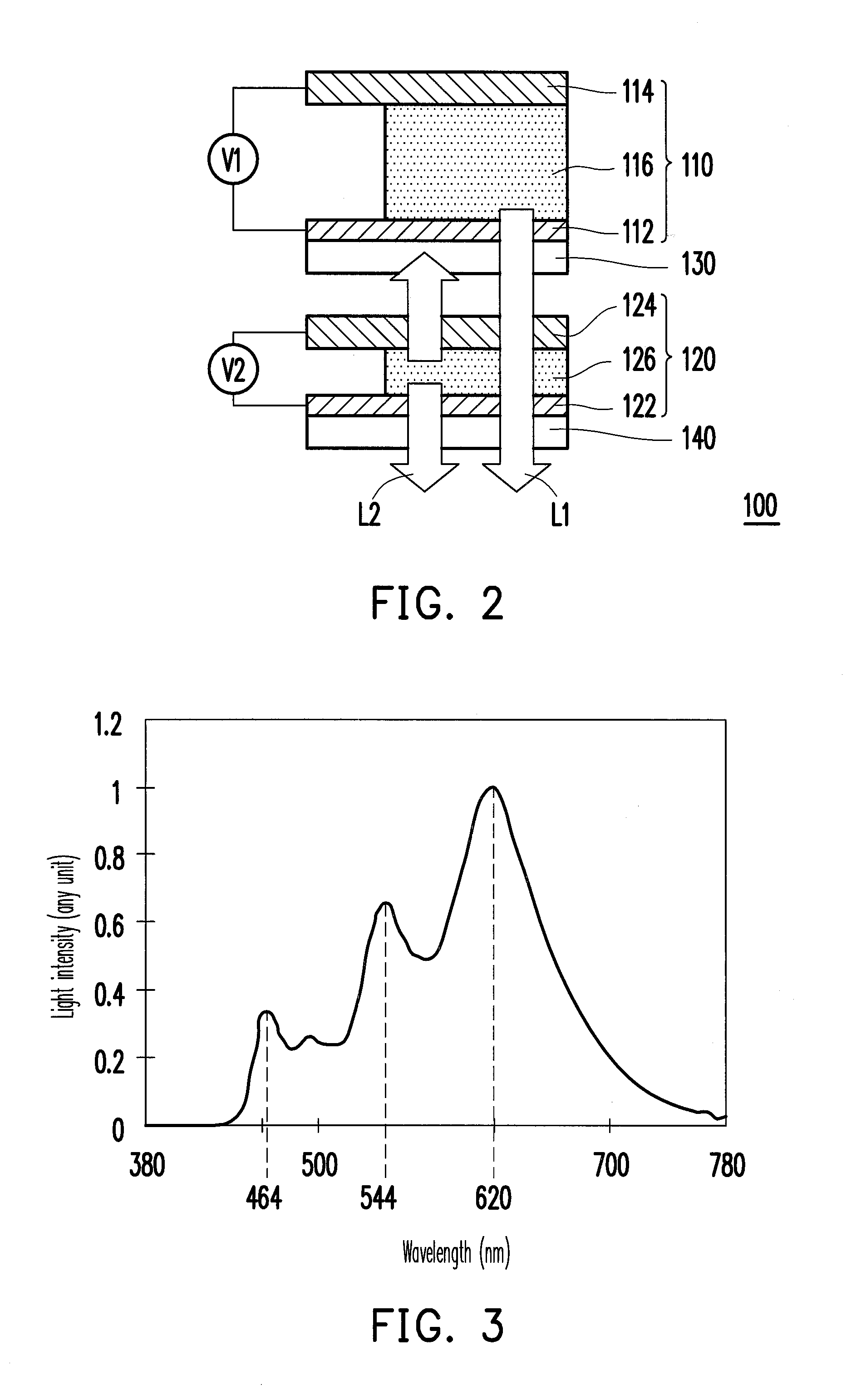
[0018]FIG. 2 is a schematic cross-sectional diagram of the organic electroluminescent light source according to a first embodiment. Referring to FIG. 2, an organic electroluminescent light source 100 of the present embodiment includes a first organic electroluminescent device 110 and a second organic electroluminescent device 120. In the present embodiment, the first organic electroluminescent device 110 is coupled to a first bias voltage V1 to emit a first color light L1 having a color temperature ranging from 2800K to 3500K. For example, the first color light L1 emitted by the first organic electroluminescent device 110 is a white light having three intensity peaks. As depicted in FIG. 3, the three intensity peaks are 464 nanometer (nm), 544 nm, and 620 nm respectively; however, the invention is not limited thereto.

[0019]Referring to FIG. 2, the second organic electroluminescent device 120 of the present embodiment is coupled to a second bias voltage V2 to emit a second color ligh...

second embodiment

[0031]FIG. 6 is a schematic cross-sectional diagram of an organic electroluminescent light source according to a second embodiment. Referring to FIG. 6, the organic electroluminescent light source 100A of the present embodiment is similar to the organic electroluminescent light source 100 in the first embodiment. However, the two light sources have some structural differences. The structural differences are illustrated in the following and the similarities of the two are not reiterated hereinafter.

[0032]The organic electroluminescent light source 100A of the present embodiment includes a first organic electroluminescent device 110 and a second organic electroluminescent device 120. The first organic electroluminescent device 110 is coupled to a first bias voltage V1 to emit a first color light L1 having a color temperature ranging from 2800K to 3500K. The second organic electroluminescent device 120 is coupled to a second bias voltage V2 to emit a second color light L2. The first co...

third embodiment

[0034]FIG. 7 depicts a schematic cross-sectional diagram of an organic electroluminescent light source according to a third embodiment. Referring to FIG. 7, the organic electroluminescent light source 100B of the present embodiment is similar to the organic electroluminescent light source 100 in the first embodiment. However, the two light sources have some structural differences. The structural differences are illustrated in the following and the similarities of the two are not reiterated hereinafter.

[0035]The organic electroluminescent light source 100B of the present embodiment includes a first organic electroluminescent device 110 and a second organic electroluminescent device 120. The first organic electroluminescent device 110 is coupled to a first bias voltage V1 to emit a first color light L1 having a color temperature ranging from 2800K to 3500K. The second organic electroluminescent device 120 is coupled to a second bias voltage V2 to emit a second color light L2. The firs...


PUM


Abstract

An organic electroluminescent light source including a first organic electroluminescent device and a second organic electroluminescent device is provided. The first organic electroluminescent device is coupled to a first bias voltage to emit a first color light having a color temperature ranging from 2800K to 3500K. The second organic electroluminescent device is coupled to a second bias voltage to emit a second color light. The first color light and the second color light mix to generate a third color light having a color temperature ranging from 3500K to 6500K.

Description

CROSS-REFERENCE TO RELATED APPLICATION[0001]This application claims the priority benefit of Taiwan application serial no. 100117780, filed May 20, 2011. The entirety of the above-mentioned patent application is hereby incorporated by reference herein and made a part of this specification.BACKGROUND[0002]1. Technical Field[0003]The disclosure relates to a light source and more particularly to an organic electroluminescent light source.[0004]2. Description of Related Art[0005]Comparing to conventional light sources such as incandescent lamps, fluorescent lamps, and the like, organic electroluminescent light source is light, mercury-free, ultraviolet radiation free, and used as a planar light source. Thus, the organic electroluminescent light source has become a new potential light source. Take a white light organic electroluminescent lamp as an example, a luminescent layer constituted by a blue organic luminescent material and a yellow organic luminescent material is mainly adopted in...

Claims


Application Information

Patent Timeline
Patent Type & Authority Applications(United States)
IPC IPC(8): H01L33/62
CPCH01L27/3206H01L2251/5361H01L2251/5323H10K59/30H10K2102/3031
Inventor LEE, MENG-TINGWU, CHANG-YENLIN, CHUN-LIANGCHEN, CHIEH-WEI
Owner AU OPTRONICS CORP
Why Eureka
Try Eureka