Precision location method and system

a location method and location technology, applied in the direction of direction finders, location information based services, instruments, etc., can solve the problems of multi-path signal contamination of known locator systems, impede the use of electronic locating systems in indoor environments, and insufficient signal strength

Inactive Publication Date: 2012-11-22
AMENDOLARE VINCENT THOMAS +2
View PDF15 Cites 30 Cited by
  • Summary
  • Abstract
  • Description
  • Claims
  • Application Information

AI Technical Summary

Benefits of technology

[0006]In accordance with these and other objects of the present invention, precision locator methods and systems are described. The present invention alleviates problems associated with known locator systems. The present invention has the capability to operate in high multi-path environments, can deliver location precisely with a relatively narrow bandwidth signal, generally does not require precise phase relationships between receiver radio frequency electronics, and does not require a pre-existing infrastructure.

Problems solved by technology

However, in the past, several factors have hindered the use of known electronic locating systems in indoor environments.
One major impediment to the use of known locator systems is multi-path signal contamination, referring to the signal scattering effect caused by the local environment between the transmitter and the receiver, such as walls, support beams, and any metal objects.
Other impediments include insufficient signal strength, lack of precision, the FCC spectrum non-compliance of ultra wide band systems, the need for pre-existing infrastructure, and failure of simple pulse distortion models in actual through-building and multi-path propagation conditions.

Method used


Image

  • Precision location method and system
  • Precision location method and system
  • Precision location method and system

Examples


Embodiment Construction

[0026]To provide an overall understanding of the invention, certain illustrative embodiments will now be described, including systems and methods for determining the location of a mobile unit. However, it will be understood by one of ordinary skill in the art that the systems and methods described herein may be adapted and modified as is appropriate for the application being addressed and that the systems and methods described herein may be employed in other suitable applications, and that such other additions and modifications will not depart from the scope thereof.

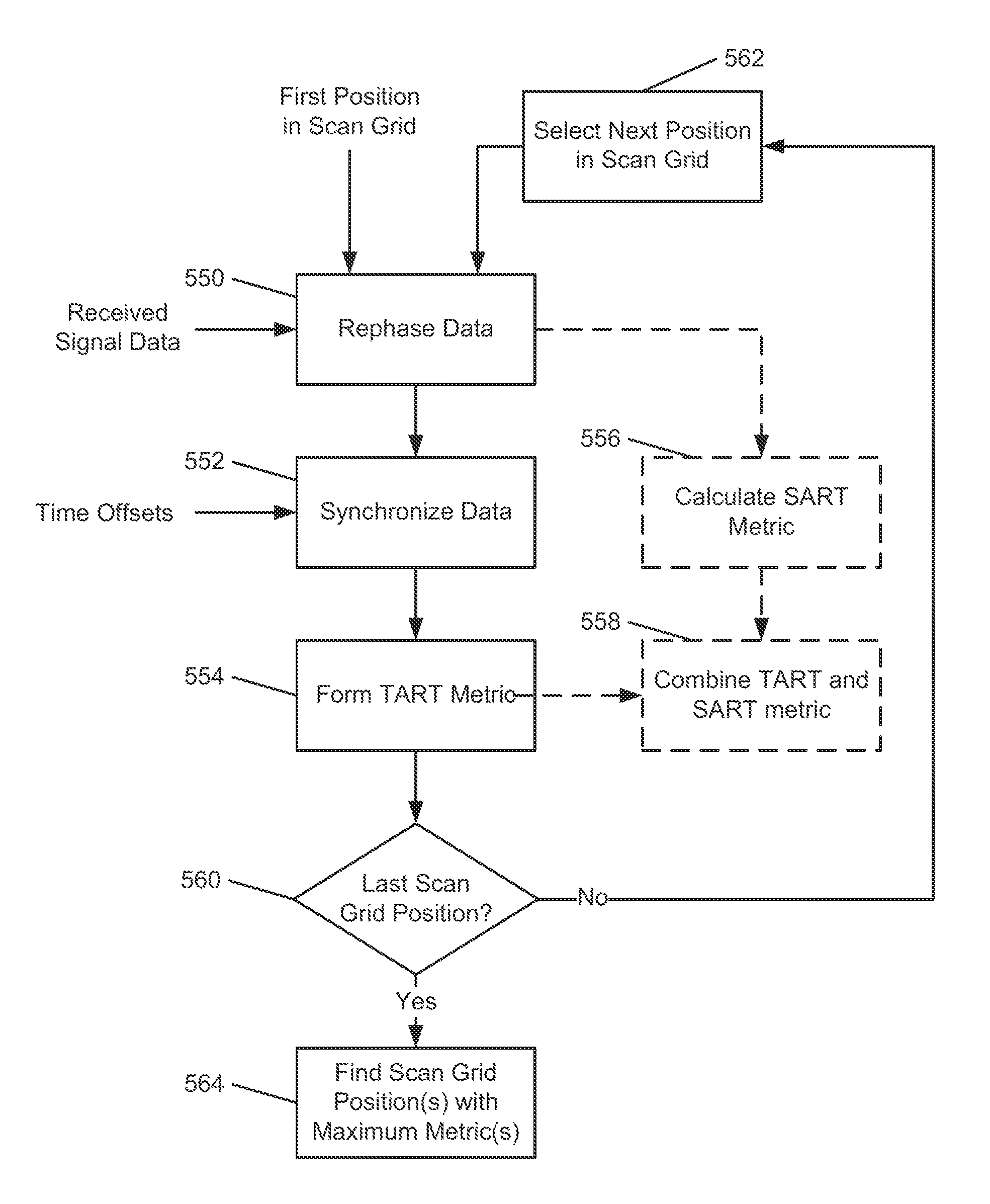
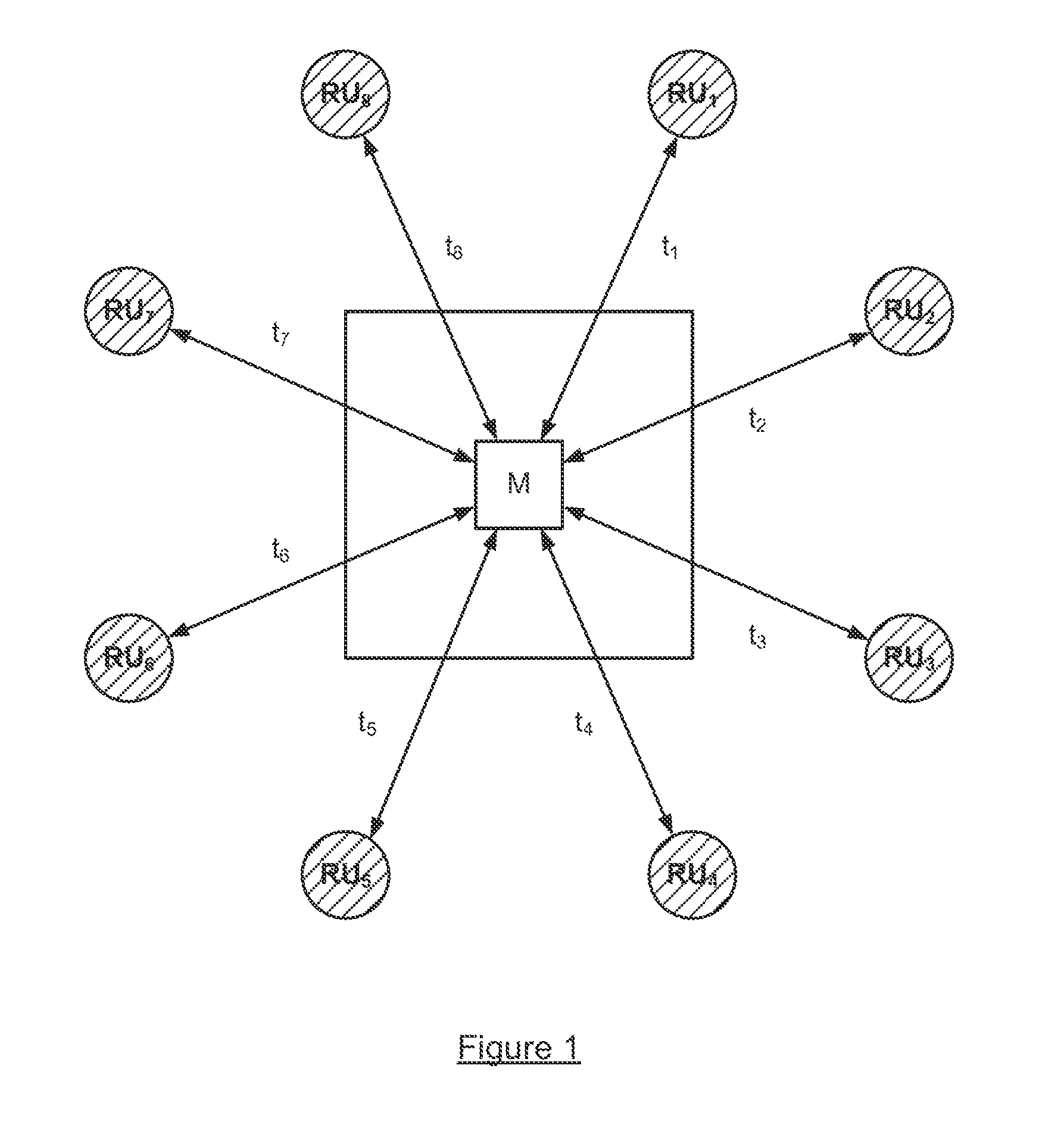
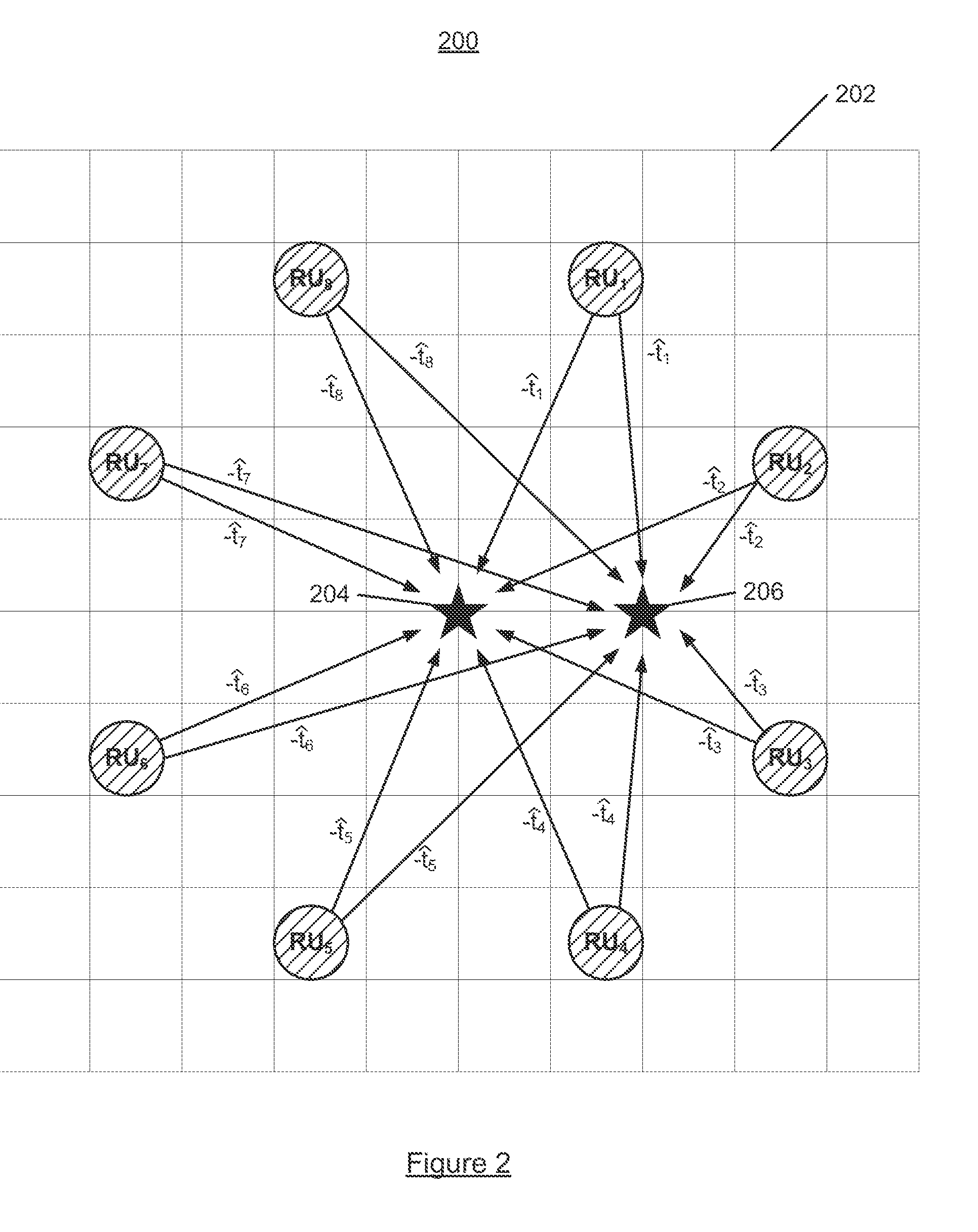
[0027]The degradation of performance caused by the multi-path signal contamination described above is generally addressed herein by application of a diversity signal combining and position solution approach. This “multi-signal fusion” approach solves for the location (in 2D or 3D space) using multiple received location signals, simultaneously and integrally, and not by combining several independently obtained time delay ...


PUM


Abstract

Systems and methods for locating an object are disclosed herein. The locator system includes a plurality of reference units and a processor in communication with the reference units. The reference units are positioned about a region in which a mobile unit is located, and each reference unit includes a transceiver for transmitting and receiving a transaction-based location signal to and from the mobile unit. The processor is configured for estimating time offsets between the mobile unit and reference units and aligning the transaction-based location signals from the reference units by removing the time offsets. The processor is further configured for collectively processing data representative of the aligned location signals based on a plurality of potential locations to identify at least one of the potential locations as a likely mobile unit location.

Description

CROSS-REFERENCE TO RELATED APPLICATION[0001]This application claims the benefit of U.S. Provisional Application 61 / 336,372 filed on Jan. 20, 2010, the entirety of which is incorporated herein by reference.FIELD OF THE INVENTION[0002]In general, the invention relates to locating objects by means of radio signals. More specifically, the invention relates to a system and method for locating objects in high multi-path environments precisely using a multi-signal fusion approach.BACKGROUND OF THE INVENTION[0003]The precise tracking of persons and / or objects is desirable in many applications. One way to achieve precision indoor location with electronic tracking systems is by ranging (estimating the distance) between one or more base stations and a mobile locator device. Known examples of electronic locating systems that perform ranging are GPS technology, in which satellite transmissions are used by mobile receivers to determine the position of the mobile receivers, and cell phone location...

Claims


Application Information

Patent Timeline
Patent Type & Authority Applications(United States)
IPC IPC(8): G01S5/02H04W4/029H04W4/33
CPCH04W4/043G01S5/02G01S5/0205G01S5/0226H04W4/33H04W4/029
Inventor AMENDOLARE, VINCENT THOMASDUCKWORTH, R. JAMESCYGANSKI, DAVID
Owner AMENDOLARE VINCENT THOMAS
Why Eureka
Try Eureka