Lighting device and lighting instrument

Inactive Publication Date: 2012-11-22
PANASONIC INTELLECTUAL PROPERTY MANAGEMENT CO LTD
View PDF4 Cites 3 Cited by
  • Summary
  • Abstract
  • Description
  • Claims
  • Application Information

AI Technical Summary

Benefits of technology

[0011]With the present embodiment, the LED light sources are divided into a plurality of LED light source groups. Each of the protector elements is electrically connected to the LED light sources of each of the LED light source groups. This makes it possible to protect the LED light sources whil

Problems solved by technology

However, if the protector element is connected to the LEDs 101, there is posed a problem

Method used


Image

  • Lighting device and lighting instrument
  • Lighting device and lighting instrument
  • Lighting device and lighting instrument

Examples


Example

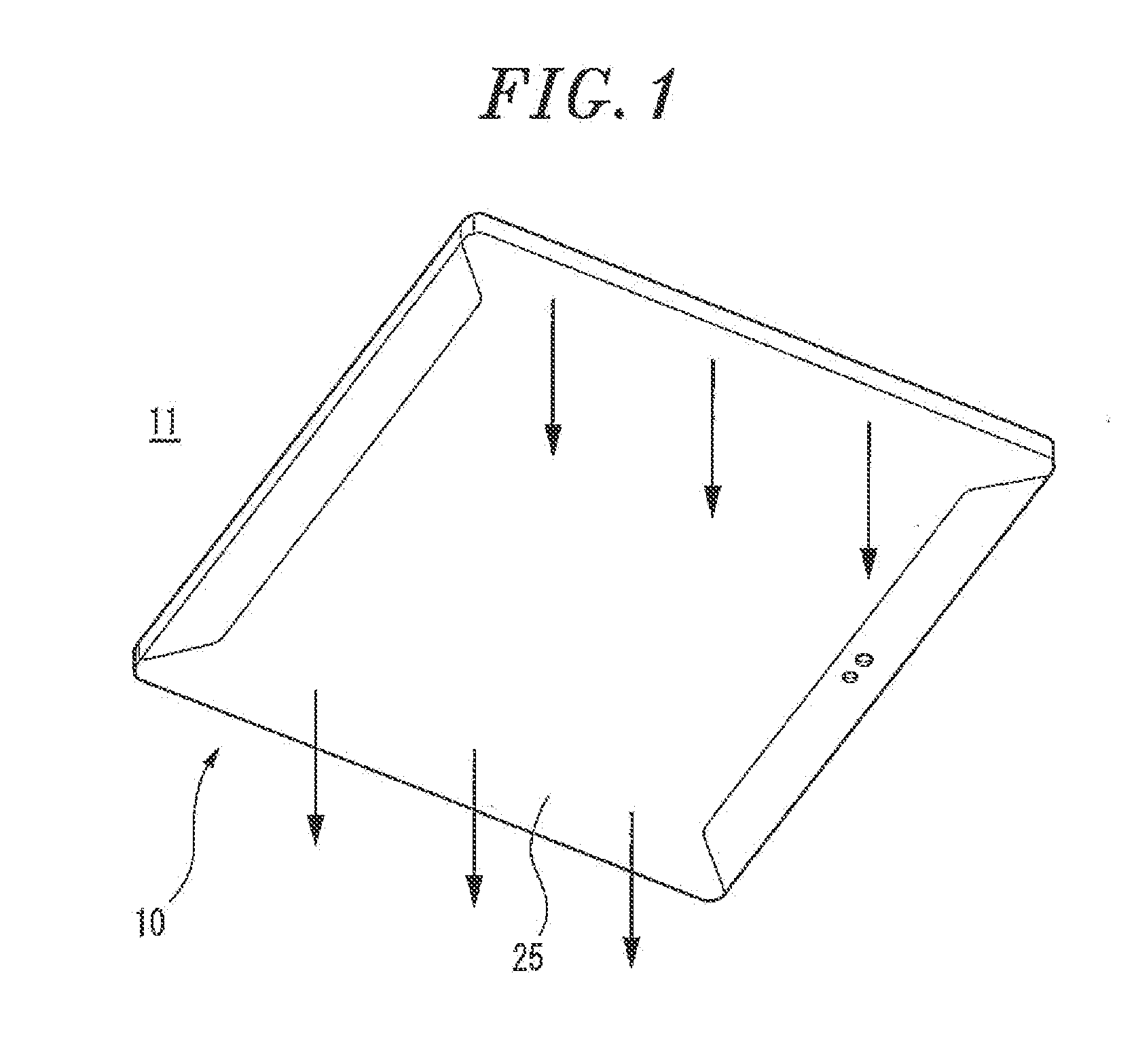
[0022]A lighting device and a lighting instrument according to a first embodiment of the present invention will now be described with reference to the accompanying drawings which form a part hereof. The following description is directed to a case in which illumination is performed by attaching a lighting instrument to a ceiling surface as a target installation surface. Unless specifically mentioned otherwise, the term “upper (upward)” denotes the side of a ceiling surface and the term “lower (downward)” signifies the side of a floor surface.

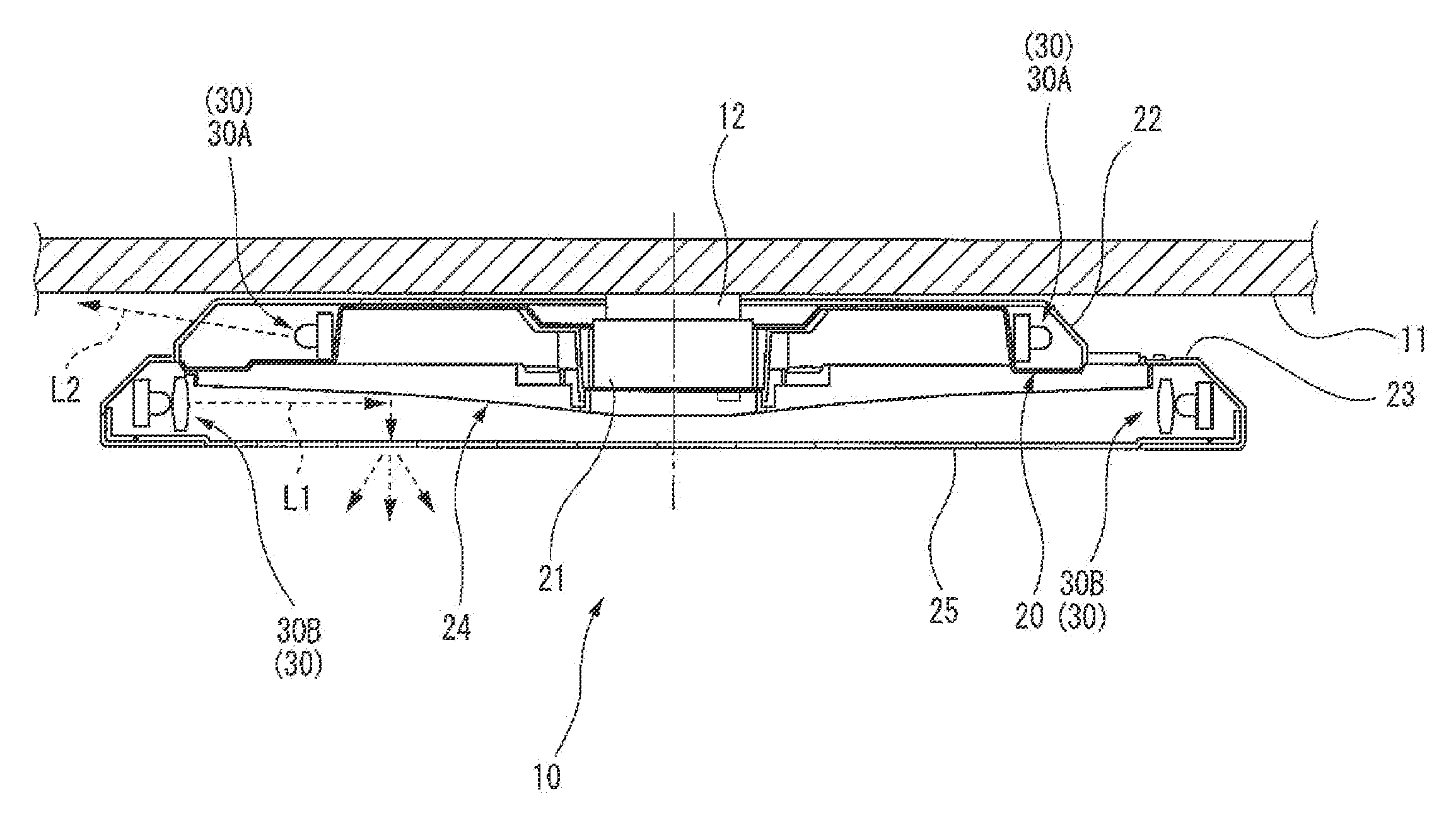
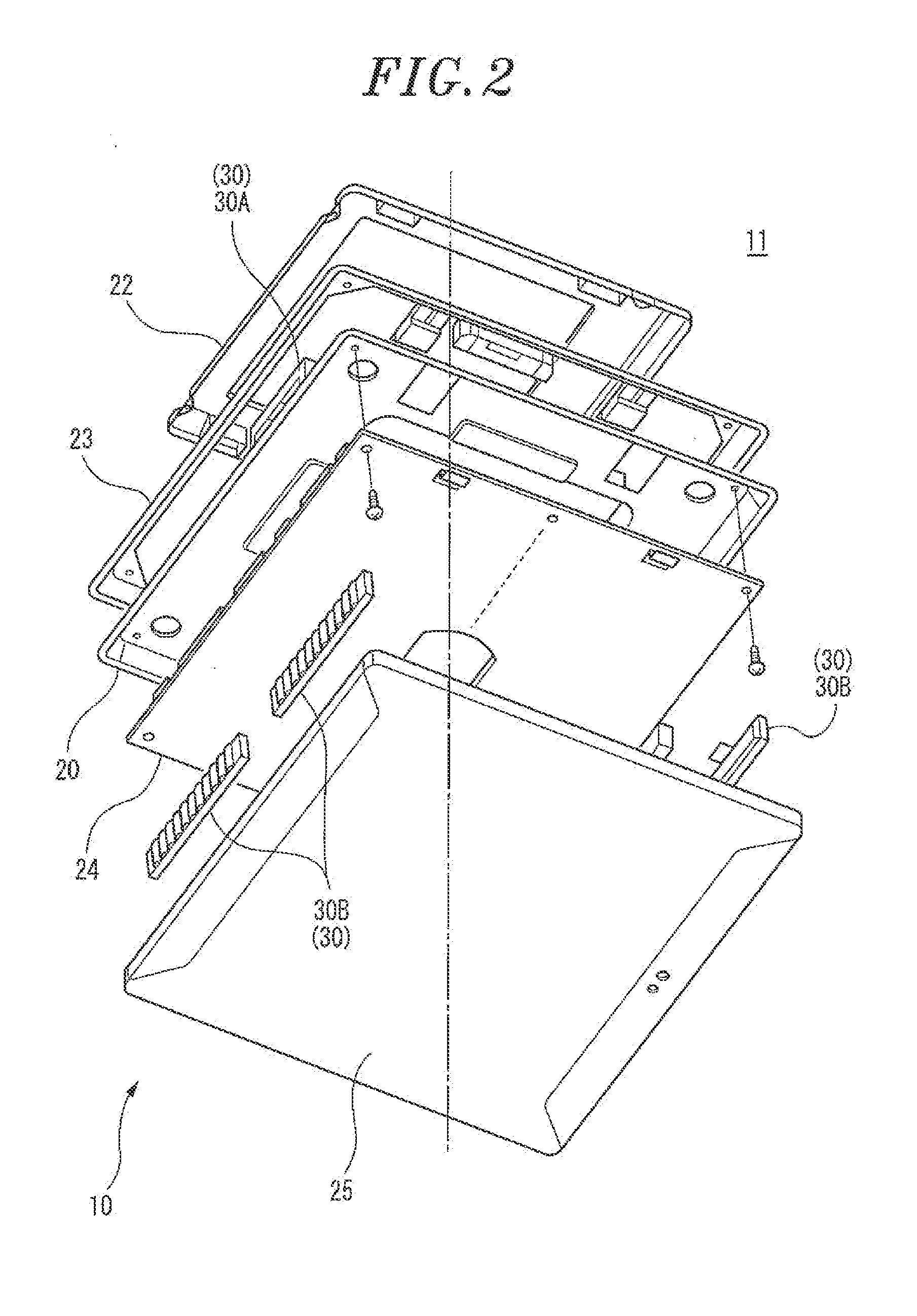
[0023]As shown in FIG. 1, the lighting instrument 10 according to a first embodiment of the present invention is attached to a ceiling surface 11 as a target installation surface and is suitable for illuminating a lower area. As shown in FIGS. 2 and 3, the lighting instrument 10 includes an instrument body 20 having, e.g., a rectangular plate-like shape. The instrument body 20 is provided at the center thereof with a clasp 21 to be attached to a ...

Example

Second Embodiment

[0049]Next, description will be made on a lighting device and a lighting instrument according to a second embodiment of the present invention. The portions common to the lighting device and the lighting instrument of the first embodiment will be designated by like reference numerals with no description made thereon.

[0050]In a LED unit 35 as the lighting device of the second embodiment, as shown in FIG. 7, a plurality of LED light sources 40C corresponding to the first LED light sources 40A of the first embodiment is mounted on the mounting surface 311 of the LED substrate 31. In other words, the LED unit 35 includes only one circuit 32C corresponding to the first circuit 32A of the first embodiment. The LED light sources 40C are serially connected by the circuit 32C.

[0051]Connectors 33 are attached to the mounting surface 311 of the LED substrate 31 and are positioned inward of the LED light sources 40 existing in the end portions of the LED substrate 31, when seen ...


PUM


Abstract

A lighting device includes a plurality of LED light sources, an LED substrate mounted with the LED light sources, and at least one protector element mounted on the LED substrate to protect the LED light sources. The LED light sources are divided into a plurality of LED light source groups. The protector element is arranged in at least one of the LED light source groups while being electrically connected to the LED light sources of each of the LED light source groups.

Description

FIELD OF THE INVENTION [0001]The present invention relates to a lighting device employing LED light sources and a lighting instrument using the lighting device.BACKGROUND OF THE INVENTION[0002]There are conventionally known lighting instruments such as a guide lamp and a signal lamp, in which an LED is used as a light source (see, e.g., Japanese Patent Application Publication No. 2007-258033, FIG. 4). As shown in FIG. 9, a lighting instrument 100 disclosed in Japanese Patent Application Publication No. 2007-258033 is a guide lamp for guiding a human to, e.g., an emergency exit. In the front portion of a box-shaped instrument body, there is provided a display plate having a design for guidance of a human to an emergency exit. An LED substrate 102 mounted with a plurality of LEDs 101 is stored within the instrument body. The LED substrate 102 is connected to an on-off unit 104 through a connector 103.[0003]The LED substrate 102 includes a plural number of LED arrays formed by alternat...

Claims


Application Information

Patent Timeline
IPC IPC(8): F21V15/00H05B44/00
CPCF21S8/026F21V23/00F21Y2101/02Y02B20/341F21V7/0008F21V23/02F21Y2103/003H05B33/0824F21Y2103/10F21Y2115/10H05B45/44Y02B20/30
Inventor MATSUMOTO, HIROYUKIOOTUBO, ATUSIKOUNO, TADAHIROMATSUZAKI, JUNYAMASHITA, KOJIMINAKI, SINSUKE
Owner PANASONIC INTELLECTUAL PROPERTY MANAGEMENT CO LTD
Why Eureka
Try Eureka