Method and apparatus for shared mesh protection switching

Active Publication Date: 2012-11-22
ELECTRONICS & TELECOMM RES INST
View PDF10 Cites 18 Cited by
  • Summary
  • Abstract
  • Description
  • Claims
  • Application Information

AI Technical Summary

Benefits of technology

[0027]As such, according to an embodiment of the present invention, the protection paths of the plurality of end-to-end linear protection domains can share the network res

Problems solved by technology

The 1+1 scheme uses a simple protocol, but has a drawback of wasting half of network resources for the protection path.
In the networks, various protection domains having different end nodes exist, but there is no mechanism that can coordinate the use of network resources between the end-to-end linear protection domains.
As a result, the protect

Method used


Image

  • Method and apparatus for shared mesh protection switching
  • Method and apparatus for shared mesh protection switching
  • Method and apparatus for shared mesh protection switching

Examples


Embodiment Construction

[0035]In the following detailed description, only certain exemplary embodiments of the present invention have been shown and described, simply by way of illustration. As those skilled in the art would realize, the described embodiments may be modified in various different ways, all without departing from the spirit or scope of the present invention. Accordingly, the drawings and description are to be regarded as illustrative in nature and not restrictive. Like reference numerals designate like elements throughout the specification.

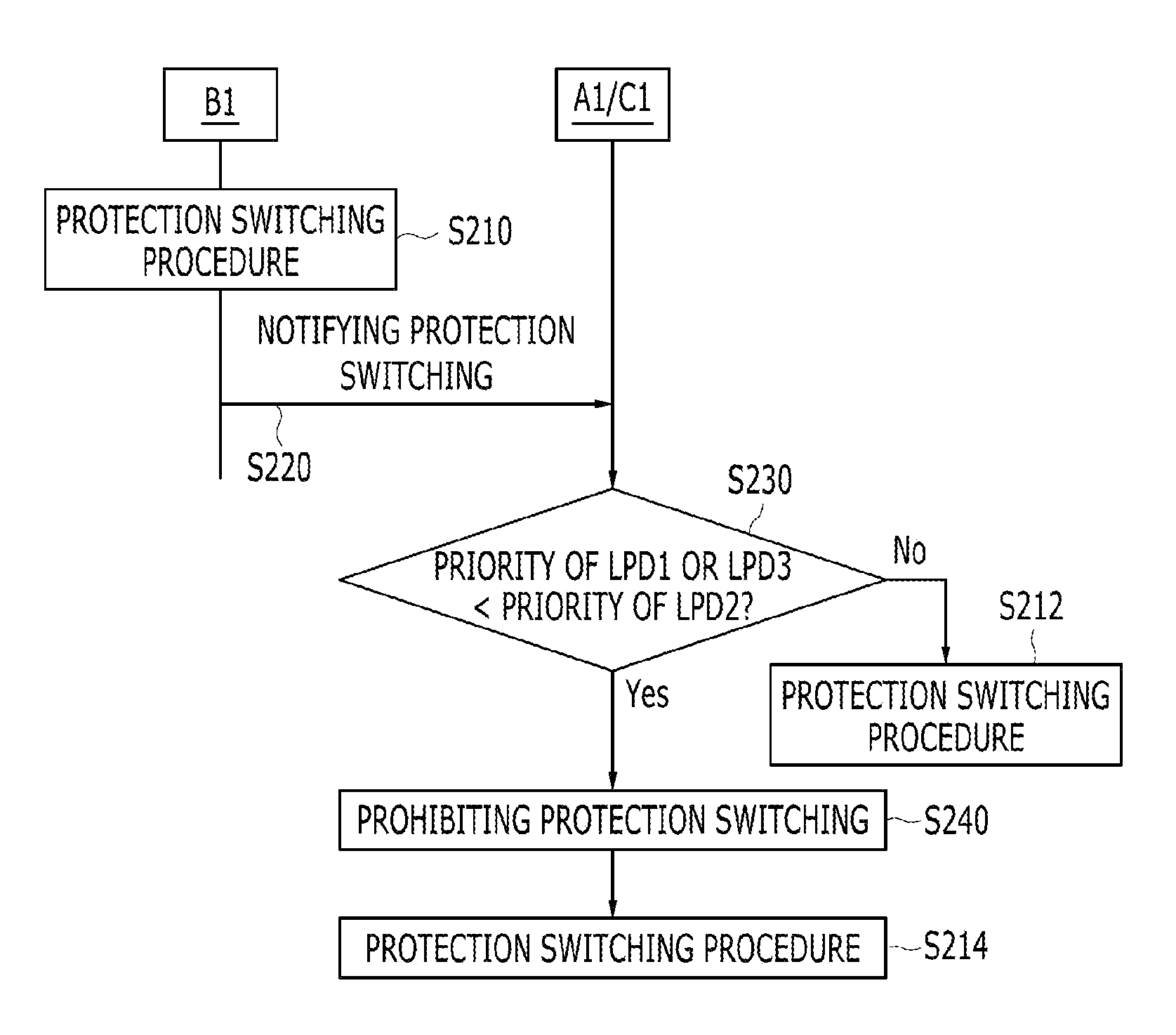
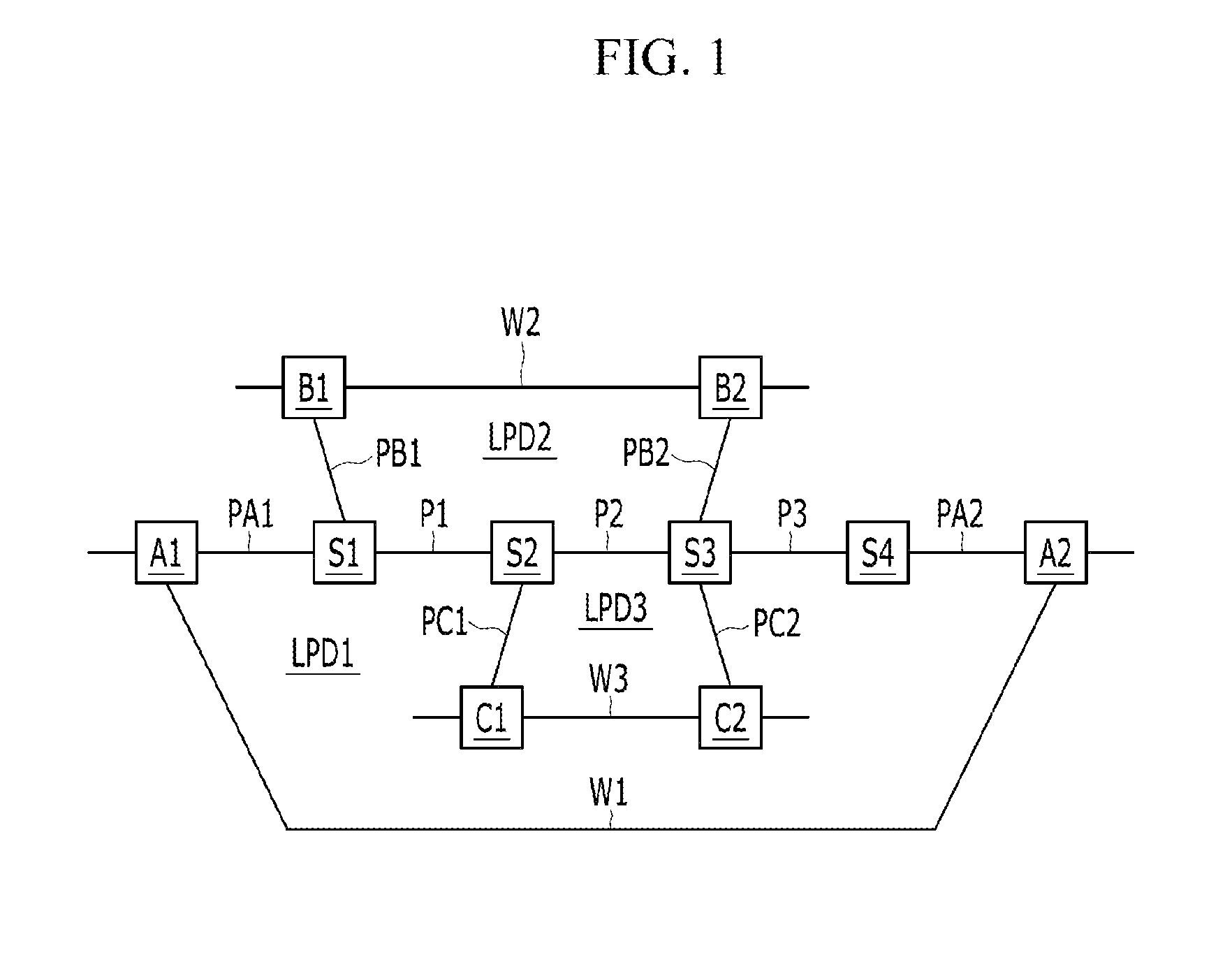
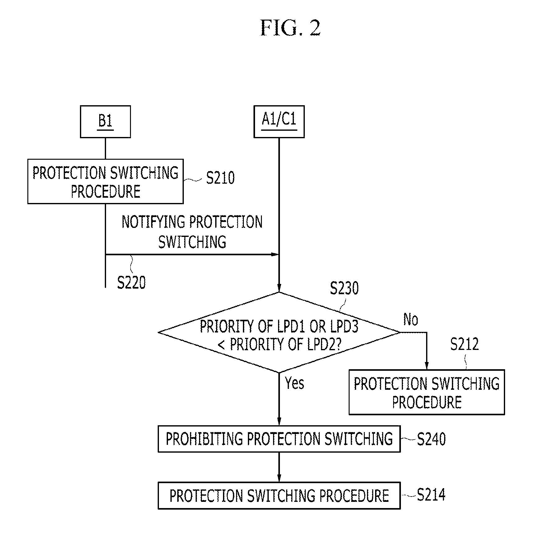
[0036]FIG. 1 shows an example of a network using a shared mesh protection switching method according to an embodiment of the present invention. FIG. 2 is a schematic flowchart showing a shared mesh protection switching method according to an embodiment of the present invention. FIG. 3 shows an example of protection switching occurrence in the network shown in FIG. 1.

[0037]Referring to FIG. 1, an example of the network includes a plurality of end-to-end lin...


PUM


Abstract

A method for protection switching in a shared node where protection resources of a plurality of end-to-end linear protection domain are shared is provided. The shared node receives a first protection switching event message notifying that a protection switching event occurs from a first node of a first end-to-end linear protection domain, and determines whether to prohibit protection switching on a second end-to-end linear protection domain by comparing a priority of the first end-to-end linear protection domain with a priority of the second end-to-end linear protection domain.

Description

BACKGROUND OF THE INVENTION[0001](a) Field of the Invention[0002]The present invention generally relates to a method and apparatus for a shared mesh protection switching.[0003](b) Description of the Related Art[0004]Protection switching is a mechanism for rerouting traffic as soon as possible when the traffic is blocked by a failure in the network. The protection switching is classified as linear protection switching and ring protection switching according to network topology, and the linear protection switching is again classified as 1+1, 1:1, 1:N or M:N protection switching.[0005]Basic protection switching scheme is 1+1 scheme. In the 1+1 scheme, there is a traffic path (hereinafter referred to as “protection path”) for protecting end-to-end traffic path (hereinafter referred to as “working path”).[0006]According to the 1+1 scheme, under normal condition, a transmitting node simultaneously transmits traffic over the working path and the protection path, and a receiving node receiv...

Claims


Application Information

Patent Timeline
IPC IPC(8): H04L29/14H04L69/40H04L45/24
CPCH04L45/24H04W76/18H04L41/0668H04L45/28H04W24/04
Inventor CHEUNG, TAE SIKRYOO, JEONG-DONG
Owner ELECTRONICS & TELECOMM RES INST
Why Eureka
Try Eureka