
Wireless communication method

Inactive Publication Date: 2012-11-22
WISTRON NEWEB
View PDF9 Cites 13 Cited by
  • Summary
  • Abstract
  • Description
  • Claims
  • Application Information

AI Technical Summary

Benefits of technology

[0019]Therefore, the advantage of the present disclosure is to establish two unidirectional wireless connections by using different channels to transmit the uplink data and the downlink data, respectively, and these two unidirectional wireless connections both can be used to perform independent data transmission in each of two different channels, in order to double the wireless communication bandwidth and to improve the wireless transmission rate.

Problems solved by technology

At this time, the other RF module of the wireless AP may be idle, and as a result, wireless network resources will be wasted.
With limited wireless bandwidth and channels, this has resulted in interference between wireless network communications becoming more and more serious.
Therefore, a heretofore unaddressed need exists in the art to cope with the aforementioned deficiencies and inadequacies.
When at least one of the wireless connections is unable to be established, the attempt to establish the connection is aborted.
When the first wireless connection and the second wireless connection are unable to be established, the attempt to establish the connection is aborted.
First, the attempt to establish the connection is aborted.

Method used


Image

  • Wireless communication method
  • Wireless communication method
  • Wireless communication method

Examples


first embodiment

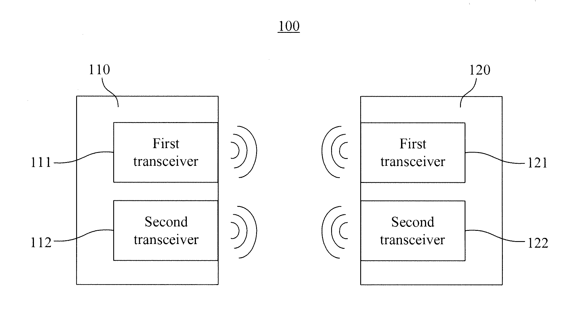
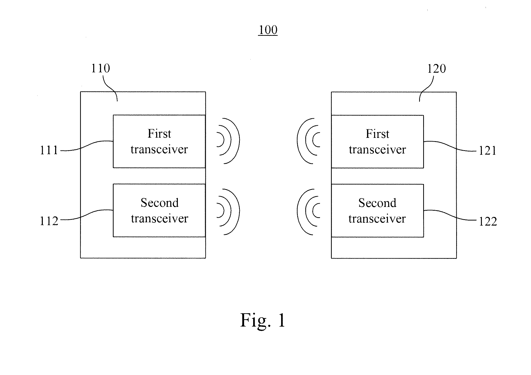
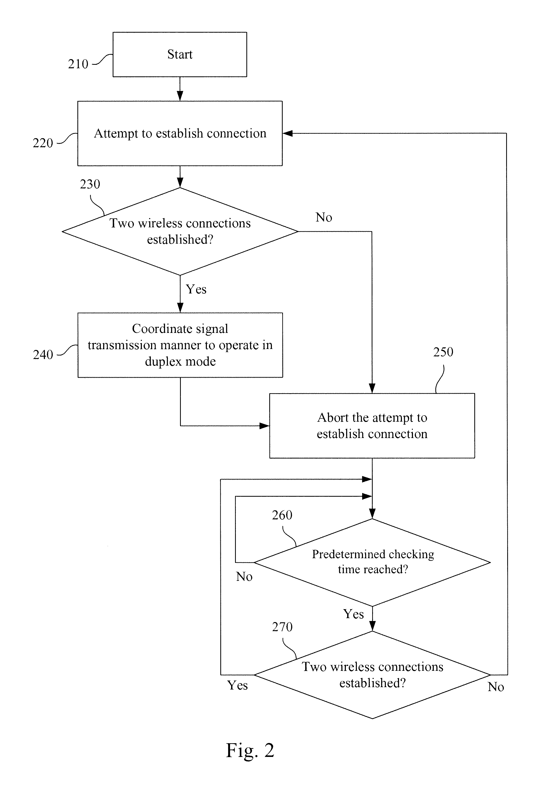
[0031]Reference is now made to both FIG. 1 and FIG. 2. A flow diagram will be described in FIG. 2 that illustrates a wireless communication method according to the present disclosure. It is noted that the present embodiment uses the same or similar wireless communication system 100 as shown in FIG. 1 to realize wireless connections, and thus a description about the structure of the present embodiment will not be repeated herein.

[0032]In operation 210, an initial process of the wireless communication system is performed. For example, the first wireless communication device 110 and the second wireless communication device 120 start to perform a searching process for available channels in this operation, in order to provide a foundation to establish the wireless connections.

[0033]In operation 220, establishing a first wireless connection is attempted, after which establishing a second wireless connection using a different channel from the first wireless connection is attempted. For exa...

second embodiment

[0039]Reference is now made to both FIG. 1 and FIG. 3. A flow diagram will be described in FIG. 3 that illustrates a wireless communication method according to the present disclosure. It is noted that the present embodiment uses the same or similar wireless communication system 100, as shown in FIG. 1, to realize wireless connections, and thus a description about the structure of the present embodiment will not be repeated herein.

[0040]In one embodiment of the present disclosure, the wireless connection is operated in the duplex mode as shown in operation 310, and further includes operations 320 to 380 as described below.

[0041]In operation 320, a determination is made as to whether a predetermined checking time is reached. For example, when the wireless connections operated between the first wireless communication device 110 and the second wireless communication device 120 enter into the duplex mode, then after the predetermined checking time is reached, determining a connection sta...

third embodiment

[0048]Reference is now made to FIG. 1, FIG. 2 and FIG. 4. A flow diagram will be described in FIG. 4 that illustrates a wireless communication method according to the present disclosure. It is noted that the present embodiment uses the same or similar wireless communication system 100 as shown in FIG. 1 to realize wireless connections, and operations 410 to 440 in the present embodiment are the same as or similar to operations 210 to 240, as shown in FIG. 2, and thus a description thereof will not be repeated herein.

[0049]In operation 450 and 460, when only one wireless connection is established, the uplink data and the downlink data are transmitted by the established wireless connection, such that a backup mode of operation is realized. For example, when only one wireless connection using the 7th channel of the 2.4 GHz band in the Wi-Fi 802.11g specification is established between the first wireless communication device 110 and the second wireless communication device 120, a 20 MHz...


PUM


Abstract

A wireless communication method includes attempting to establish a first wireless connection. Next, an attempt is made to establish a second wireless connection using a different channel from the first wireless connection. Subsequently, a determination is made as to whether the first wireless connection and the second wireless connection are established. When the first wireless connection and the second wireless connection are established, a manner of signal transmission between the first wireless connection and the second wireless connection is coordinated to transmit uplink data and downlink data, respectively, such that a duplex mode of operation is realized.

Description

RELATED APPLICATIONS[0001]This application claims priority to Taiwan Application Serial Number 100117617, filed May 19, 2011, which is herein incorporated by reference.BACKGROUND[0002]1. Field of Invention[0003]The present disclosure relates generally to an electronic communication method, and more particularly to a wireless communication method.[0004]2. Description of Related Art[0005]In order to provide a network connection service using different wireless network communication specifications such as Wi-Fi 802.11a / b / g / n, conventional wireless access points (APs) may be equipped with two radio frequency (RF) modules operating in different frequency bands (e.g., a 2.4 GHz frequency band and a 5 GHz frequency band) to provide the network connection service for clients or other wireless APs operated using different wireless network communication specifications.[0006]However, a wireless AP equipped with two RF modules may use only one RF module at a time to perform a wireless connectio...

Claims


Application Information

Patent Timeline
IPC IPC(8): H04W72/04
CPCH04W76/02H04W76/10
Inventor WANG, YI-PINGHO, YUNG-FA
Owner WISTRON NEWEB
Learn More